Aligning Project Photos to a Reference Source
PhotoMesh provides three alignment methods for anchoring your project's photo collections to a known geographic reference. This is essential when combining multiple datasets for the same geographic region or aligning a project with external data when GPS accuracy is limited or unavailable.
§ Align to a Reference Project – Aligns photos in your current project to those of a previously built project with overlapping coverage.
§ Align to a 3D Layer – Aligns photos to a mesh model or orthophoto+DSM layer generated in other software, without requiring access to the original source photos.
§ Align to LiDAR – Aligns the project's photos and LiDAR datasets, ensuring precise georeferencing and optimized mesh reconstruction, without the need for manual control points.
Each option supports one or both of the following modes for generating reference snapshots:
§ Auto-Generate Aerial Grid-Based Pattern – Creates reference snapshots in a regular grid over the area of interest.
§ Follow Original Acquisition Pattern – Reconstructs reference snapshots based on the camera angles and flight path of the original photo capture, used to generate the project’s mesh.
Aligning Project Photos to a Reference Project
Adding a reference project allows you to align the photos in your current project with the geographic location of photos from another project that covers the same area. This is especially useful when the two projects partially or fully overlap and will be displayed together in a client viewer. PhotoMesh uses the older "base" project as a reference project for the new "target" project, to establish a correspondence between the two so that the positions of identified features in the target project match the geographic positions of the same features in the reference project.
This approach is particularly effective when working with multiple flights over the same region. Ground control points or high accuracy GPS locations (RTK, PPK) can be used for the first flight and then the reference project mechanism can be used to accurately register the other flights, even without GCP’s or accurate location information (e.g., in GPS-denied areas).
The Quality Report’s “Photo Matches to Reference Project Map” can be used to assess the degree of photo overlap between photos in the main-base project and the reference project data. See “Photo Matches to Reference Project Map” in the “Reviewing Your Build” chapter for more information.
To add a reference project:
1. On the Home tab, in the Add group, click the arrow under Add Reference Project and select Align Photos to Reference Project. The Add Reference Project dialog is displayed.
2. Browse to the required reference project, i.e., the calculated AT of that build (ATResult*.sqlite), and click Open. The project’s photos and photo and collection parameters are loaded into the project. When the aerotriangulation step of the build process is performed, your project will be automatically aligned to the reference project.
Aligning Project Photos to a Reference 3D Layer
PhotoMesh allows you to align projects' photo collections with geospatial layers, such as mesh models or Orthophoto+DSM, generated in other software, even when their original source photos are unavailable. This is accomplished by generating simulated reference snapshots from the external layer, which contains embedded geographic information.
These reverse-engineered snapshots serve as virtual photo references that can be aligned with the current project's photo set, effectively transferring accurate geolocation data to your project. This method is especially valuable when the project's input photos lack GPS data, have low positional accuracy, or were captured in GPS-denied environments. In addition to correcting or enhancing photo positioning, this capability enables precise alignment of new projects with existing 3D datasets.
To generate reference photos:
1. On the Home tab, in the Add group, click the arrow under Add Reference Project and select Align Photos to 3D Layer. The Align Photos to 3D Layer dialog is displayed.
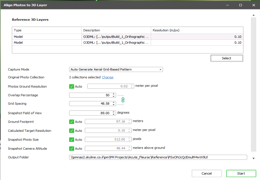
Align Photos to 3D Layer Dialog
2. In the Reference 3D Layers section, click Select to select the 3DML and Orthophoto + DSM sources for which you want to generate reference photos with camera positioning data. The Sources Selection dialog is displayed, showing all mesh, imagery and elevation layers that were loaded into the project from the Tools tab. See "Adding Terrain Objects and Layers" in the “Tools” chapter for more information/
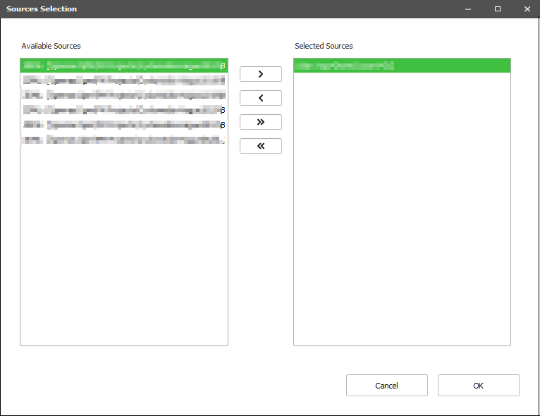
3. In the Available Sources section, select a required source, and click Insert ![]() to insert it in the Selected Sources section. If you want to remove a source from the Selected Sources section, select the source, and click Remove
to insert it in the Selected Sources section. If you want to remove a source from the Selected Sources section, select the source, and click Remove ![]() . Use Insert All
. Use Insert All ![]() and Remove All
and Remove All ![]() to insert/remove all sources. Click OK.
to insert/remove all sources. Click OK.
4. In the Capture Mode field, select the mode for generating the reference snapshots:
§ Auto-Generate Aerial Grid-Based Pattern - Reference snapshots are created in a regular grid over the area of interest, simulating the flight pattern and coverage of typical aerial photo acquisition for the mesh model.
§ Follow Original Photo Pattern - The generated reference snapshots are based on the camera angles and positions of the original photo capture, used to generate the project’s mesh.
5. In the Original Photo Collection field, click Change to choose the photo collections to use in generating the reference photos. In the Available Collections section, select a required collection, and click Insert ![]() to insert it in the Selected Collections section. If you want to remove a collection from the Selected Collections section, select the source, and click Remove
to insert it in the Selected Collections section. If you want to remove a collection from the Selected Collections section, select the source, and click Remove ![]() . Use Insert All
. Use Insert All ![]() and Remove All
and Remove All ![]() to insert/remove all collections. By default, all collections are selected.
to insert/remove all collections. By default, all collections are selected.
§ In Follow Original Photo Pattern mode, the selected collections provide the original camera angles and positions that serve as the basis for generating the reference snapshots.
§ In Auto-Generate Aerial Grid-Based Pattern mode, the reference snapshots are based on the camera angles and flight path of the original photo capture, used to generate the project’s mesh. The selected collections are used to calculate the ground footprint and resolution of the reference snapshots.
6. In the General Settings section, in the Output path field, click Browse, and browse to the folder in which to save the generated snapshots.
7. If Auto-Generate Aerial Grid-Based Pattern is selected, set the following properties:
§ Overlap Percentage: Percentage of overlap between adjacent snapshots. Higher values produce more redundancy and better alignment.
§ Grid Spacing: Distance between adjacent snapshots in the grid (in meters).
§ Snapshot Field of View
PhotoMesh auto-calculates the following values. If you want to set your own values, clear the Auto check box, and enter a value.
§ Photos Ground Resolution: Horizontal viewing angle of the simulated camera.
§ Ground Footprint: Size on the ground that each photo covers, estimated from original collections.
§ Calculated Target Resolution: The lower value between the average resolution of the selected sources and the resolution of the selected collections.
§ Snapshot Photo Size: Size of the generated photos in pixels, derived from the footprint and resolution.
§ Snapshot Camera Altitude: Calculated camera height to ensure correct photo scale and coverage.
8. If Follow Original Photo Pattern is selected, set the following properties:
§ Snapshot Orientation – Select either: Use Original Orientation - Each generated snapshot's camera position and angle are based on those of the original photo or Generate Four Snapshots Around Original Position – Four oblique snapshots are generated for each original photo, to allow inspection from multiple sides.
§ Snapshot Altitude Offset from Original - Offset to add to the original photos’ altitude.
§ Snapshot Sampling Interval - Automatically calculated value that determines how frequently snapshots are sampled. If you want to set your own value, select the override check box, and enter a value.
9. Set the Output Folder in which to save the generated snapshots.
10. Click Start. PhotoMesh generates the snapshots based on your settings and adds them as a reference collection.
Note: When building the project, set all accuracy factor properties in the Build Settings to Unreliable. This allows the project photos to align with the reference photos during the aerotriangulation step of the build process. See “Setting Build Steps, Parameters, and Outputs” in the “Building” chapter for more information.
Aligning Project Photos to LiDAR
PhotoMesh projects's photo collections and LiDAR datasets can be aligned, ensuring precise georeferencing and optimized mesh reconstruction, without the need for manual control points.
To generate reference photos:
1. On the Home tab, in the Add group, click the arrow under Lidar and select Align Photos to Lidar. The Align Photos to Lidar dialog is displayed.
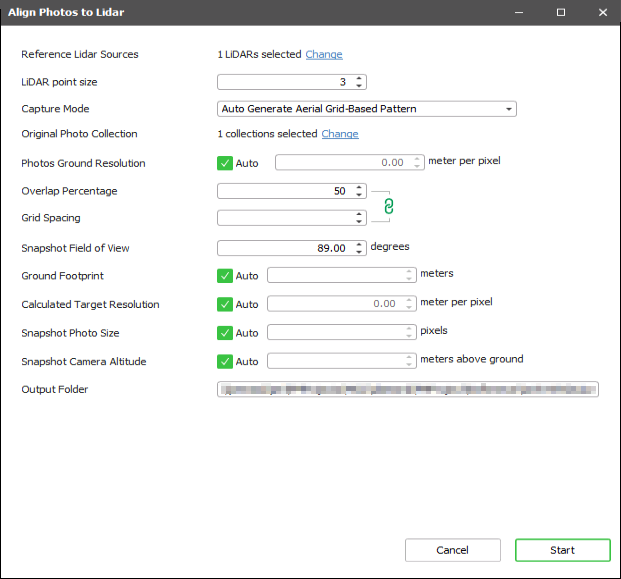
Align Photos to Lidar Dialog
2. In the Reference Lidar Sources property, click Change to select the LiDAR sources for which you want to generate reference photos with camera positioning data. The Sources Selection dialog is displayed, showing all LiDAR point clouds in the project.
3. In the Available Sources section, select a required source, and click Insert ![]() to insert it in the Selected Sources section. If you want to remove a source from the Selected Sources section, select the source, and click Remove
to insert it in the Selected Sources section. If you want to remove a source from the Selected Sources section, select the source, and click Remove ![]() . Use Insert All
. Use Insert All ![]() and Remove All
and Remove All ![]() to insert/remove all sources. Click OK.
to insert/remove all sources. Click OK.
4. Enter the following information:
|
LiDAR Point Size |
Size LiDAR source will be rendered in for generating the reference snapshots. |
|
Capture Mode |
Select the mode for generating reference snapshots from the LiDAR dataset: § Auto-Generate Aerial Grid-Based Pattern – The snapshots are generated in a regular grid over the area of interest, simulating a typical aerial photo acquisition pattern. The selected collections are used to calculate the ground footprint and resolution of the reference snapshots. § Follow Original Photo Pattern - The selected collections provide the original camera angles and positions that serve as the basis for generating the reference snapshots. |
|
Original Photo Collection |
Click Change to choose the photo collections to use in generating the simulated snapshots. In the Available Collections section, select a required collection, and click Insert § In Follow Original Photo Pattern mode, the selected collections provide the original camera angles and positions that serve as the basis for generating the reference snapshots. § In Auto-Generate Aerial Grid-Based Pattern mode, the collections are used to calculate the ground footprint and resolution of the reference snapshots. |
|
Output Folder |
Folder in which to save the generated snapshots. |
5. If you selected "Auto Generate Aerial-Based Pattern" as the Capture Mode, enter the following information:
|
Overlap Percentage |
Percentage of overlap between adjacent snapshots. Higher values produce more redundancy and better alignment |
|
Grid Spacing |
Distance between adjacent snapshots in the grid (in meters). |
|
Snapshot Field of View |
|
6. PhotoMesh auto-calculates the following values. If you want to set your own values, clear the Auto check box, and enter a value.
|
Photos Ground Resolution |
Horizontal viewing angle of the simulated camera |
|
Ground Footprint |
Size on the ground that each snapshot covers, estimated from original collections. |
|
Calculated Target Resolution |
The lower value between the average resolution of the selected sources and the resolution of the selected collections |
|
Snapshot Photo Size |
Size of the generated snapshots in pixels, derived from the footprint and resolution. |
|
Snapshot Camera Altitude |
Calculated camera height to ensure correct photo scale and coverage. |
7. If you selected "Follow Original Photo Pattern" as the Capture Mode, enter the following information:
|
Snapshot Orientation |
Select either: Use Original Orientation - Each generated snapshot tries to simulate the camera position and angle of the original photo or Generate Four Snapshots Around Original Position – Four oblique snapshots are generated for each original photo, to allow inspection from multiple sides. |
|
Snapshot Altitude Offset from Original |
Offset to add to the original photos’ altitude. |
|
Snapshot Sampling Interval |
Automatically calculated value that determines how frequently snapshots are sampled. If you want to set your own value, select the override check box, and enter a value. |
8. Click Start. PhotoMesh generates the snapshots based on your settings and adds them as a reference collection.
Note: When building the project, set all accuracy factor properties in the Build Settings to Unreliable. This allows the project photos to align with the reference photos during the aerotriangulation step of the build process. See “Setting Build Steps, Parameters, and Outputs” in the “Building” chapter for more information.
Reference Photos List
In the Reference Photos list, you can view but not edit the properties of the photos in your reference projects. See "Modifying Photo and Photo Collection Properties" in the "Photo Management" chapter for information about the photo properties.
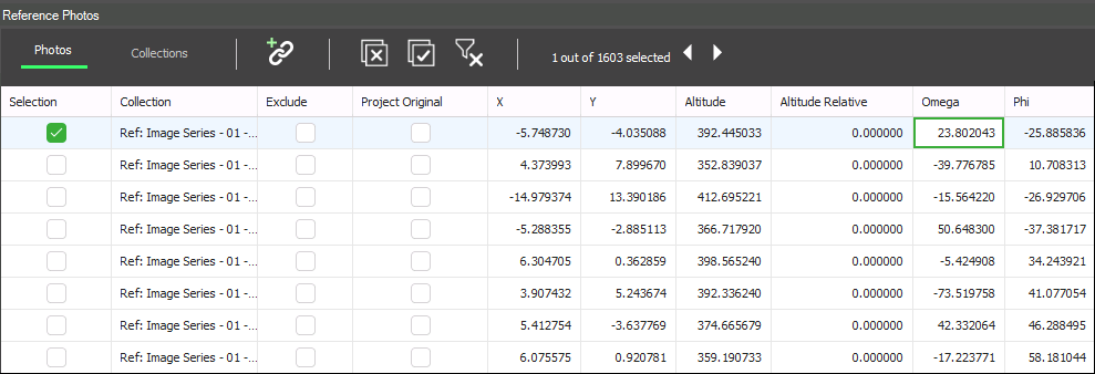
Reference Photos List