Imagery Acquisition
The first step in the PhotoMesh process entails photographing all visible surfaces of the intended object or scene from multiple overlapping viewpoints. PhotoMesh supports standard image formats and large frame sensors.
The accuracy of the resulting 3D mesh model is affected by several factors including: input photo resolution and quality, lens distortion, overlapping ratio, directionality, and lighting. While PhotoMesh optimizes the accuracy of the 3D mesh model by selecting the best photos for an area, each factor can affect the overall output or cause varying levels of accuracy and quality in different areas of a project.
In most projects with good quality input, the resolution of the 3D model has been found to be approximately 1-2 times the ground sample distance of the source imagery.
Input Format and Resolution
|
Input Format/Data |
|
|
Image Format |
Standard image formats (JPG, TIF, IIQ, etc.). |
|
Positioning Information |
XY coordinates and altitude of each photo. |
|
Orientation Information |
Omega, Phi, Kappa values (Recommended for large scale projects). |
|
Camera |
|
|
Large Frame Sensors (100+ Mega Pixel) |
Supported. |
|
Focal Length |
Photos with different focal lengths are supported. |
|
Digital Zoom |
No. |
Directionality
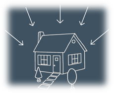
Since PhotoMesh models can be viewed from any angle, it is important to capture nearly all visible surfaces, including walls and facades. Any object in the area of interest should be photographed multiple times from the top and at least four other directions.
Overlap
To create an accurate 3D model, each point in the area of interest should be visible in multiple photos. A >66% overlap between consecutive photos is recommended. Each point in the area of interest should be visible by, at least, 3 cameras (min 10° offset). PhotoMesh can combine photos with different ground resolutions.
For structured aerial photography
§ Overlap in direction of flight (forward overlap) – 75 - 90% (recommended - 80%)
§ Overlap between neighboring rows (side overlap) – 70 - 90% (recommended - 80%)

Structured Aerial Photography Recommendations
The following guidelines are recommended for optimal model accuracy and texture quality:
§ Capture time – Avoid long shadows and sun reflections
§ Capture date – Capture all photos in the same season
§ Collection system – Use stable platforms with minimal smearing
Data Collection Recommendations for Photos
This section outlines Skyline’s recommendations for optimal 3D PhotoMesh production from collected data:
§ Camera and lens combinations (hardware preferences)
§ Camera settings and image format
§ Flight planning and execution
Camera and Lens Combinations (Hardware Preferences)
The following factors in sensor and lens selection are critical for 3D model geometry and quality:
§ A high quality lens, with minimal distortion.
§ Fixed focal length - to avoid alternating focal lengths in photos which are meant to be processed in the same dataset.
§ For a standard grid collection pattern, it is important to have a lens with a field of view (FOV) at least 90 degrees wide in the long axis (60 degrees in the short axis, ~108 degrees in diagonal).
§ A FOV < 120 degrees in the long axis, since these lenses tend to be fish-eye and too distorted for high-quality aerotriangulation.
§ A lens which can maintain sharpness in the edges of the image - for proper aerotriangulation and texturing of facades in the 3D model.
§ A sensor which can collect images rapidly - to maintain high overlap collection in low altitude flights while achieving proper overlap.
Camera Settings and Image Format
The following camera settings are recommended:
§ Disable any "auto-rotate" options, to ensure that all of the images maintain a uniform orientation during the flight.
§ Avoid slow shutter speed (generally < 1/1000) since it will cause significant motion blur, resulting in photos that cannot be used in the PhotoMesh production process. Instead of allowing a shutter speed drop to 1/640 or 1/500, it is preferable to open up the aperture value as wide as possible, even at risk of slight softness at the corners of the image. It is also possible to increase the ISO value in high quality cameras, and still maintain non-grainy images with high dynamic range in bright and dark areas.
§ Disable any settings which might affect the relative location of the lens to the sensor, such as anti-shock or vibration features, since this will create a random principal point for the camera model. Vibration or motion in the UAV stabilization platform should be addressed with the camera and lens combination as a static object.
§ Avoid auto-focus or automatic zoom. Focus the lens (usually to infinity) and lock it in that position.
§ Use full resolution format, so that it is not down-sampled from the sensor pixels.
§ Collect the photos in full uncompressed format. If JPEG format is necessary, use minimum compression to avoid artifacts or missing information in the images.
Flight Planning and Execution
The following flight patterns and execution are recommended:
§ For single building or small area collection, use a circular flight pattern, with the target area in the center of the image from all perspectives.
§ For large scale collection, use a grid pattern which allows for efficient area collection with the goal of creating 3D products.
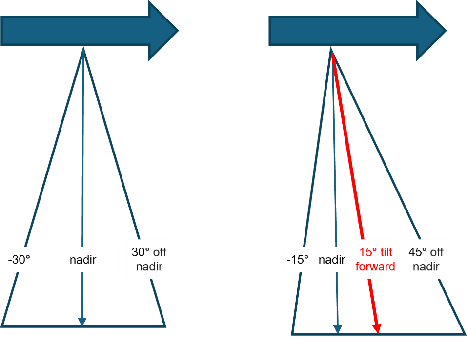
§ For nadir cameras with a field of view of approximately 60 degrees, tilt the camera 10-15 degrees forward to achieve the necessary 40-45 degree oblique perspective in all directions.
§ Maintain a frontal (vertical) overlap of 75 - 90% (recommended - 80%).
§ Maintain a side (lateral) overlap of 70 - 90% (recommended - 80%).
Mobile Photography
The following perspective and overlap are recommended for optimum reconstruction results:
§ Perspective – Capture required objects and facades at a perpendicular angle and at a 30 degree oblique variance (60 and 120 degrees) to maximize triangulation quality, while minimizing perspective distortion. In close-range data collection, any perspective which captures the object or façade at more than a 45 degree oblique will most likely be at a considerably lower resolution to provide effective input for the reconstruction.
§ Sky – Limit the sky component in the photo to no more than 30%. This can be achieved by setting the tripod to a higher altitude when possible, as well as by slightly angling the camera down (instead of pointing the camera directly at the horizon, 90 degrees from the ground, it can be angled 70-80 degrees from the ground).
§ Overlap – Maintain at least an 80% overlap, so that each object will appear in at least five photos. This provides PhotoMesh with the data to fill in holes in planes and facades that are partially obstructed by objects (such as trees and street furniture) which are closer to the camera.
Data Collection Recommendations for Full Motion Video (FMV)
This section outlines Skyline’s recommendations for optimal 3D PhotoMesh reconstruction from full motion video. The recommendations below are for oblique data. It is generally recommended to use nadir video datasets only for production of orthophotos or point clouds, and not for full 3D Mesh models.
Video Camera – Hardware and Settings
§ Use video setting most suitable for sharp video frames in motion.
§ Use gyroscope or accelerometer-based gimbal or other 3-axis stabilization.
Flight Planning and Execution
§ Slow flight to prevent motion blur.
§ Minimum field of view - 45 degrees (optimal: 60-100 degrees), depending on the lens quality.
§ Minimum lateral (side) overlap - 40% (optimal: 60-80%).
§ Minimum overlap between consecutive photos - 60%. This can be achieved by a combination of flight speed and frame rate.
§ It is recommended to use consistent zoom, especially in random flight patterns.
§ For large area collection, use a criss-cross grid pattern.
§ For single building or small area collection, video the target feature from different altitudes, and different pointing angles for complete coverage.
Photo Pre-Processing Recommendations for Non-Optimal Illumination Conditions
When dealing with sub-optimal lighting or camera settings unsuited to the data's light level, it is advisable to pre-process the photos before importing them into PhotoMesh for final processing. This step is especially critical when converting high-bit depth data (such as 12-bit or 16-bit) to a lower bit depth format (like 8-bit TIFF or minimally compressed JPG).
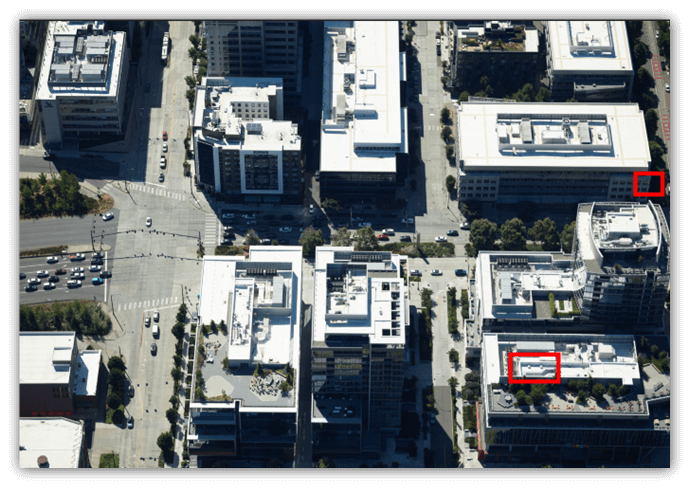
Unprocessed photos often have a high-contrast histogram, accentuating brightness variations, as seen in brightly lit areas next to shadows or dark roads beside light sidewalks. While visually striking, these photos may not be suitable for detailed analysis or processing.
Pixel-based correlation, which requires high detail at the image's native resolution, becomes particularly challenging for photos captured in environments with extreme lighting conditions. In such settings, disparities in light and shadow are more pronounced, negatively impacting the accuracy of 3D modeling.
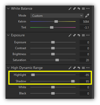
To address these issues, adjustments on the histogram's edges are recommended, particularly shadow and highlight corrections (see below), along with white balance adjustments to establish a neutral gray color scheme. A slight increase in saturation can also enhance non-gray elements, achieving a more even pixel value distribution.
|
Before |
After |
|
|
|
|
|
|
|
|
|

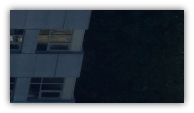
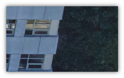
These adjustments effectively reduce the contrast between shadowed and brightly lit areas, resulting in a more balanced histogram. This balance is critical for two reasons: it improves 3D correlation by ensuring consistent feature detection across images, and it aids in smoother texture blending, thus enhancing the visual coherence of the 3D model.
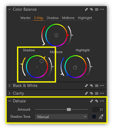
Further refinements include dehaze and minor color balance adjustments in the shadows and highlights to compensate for Rayleigh Scattering. The extent of dehazing required depends on the visibility conditions during data collection. Adjustments to shadows and highlights should be tailored to match the light intensity and the contrast between illuminated and shaded areas.