Retouching a Mesh Layer
PhotoMesh’s Manual Retouch tool allows you to correct mesh imperfections, such as bumps, irregular surfaces, or floating artifacts. Using this tool, you can mark areas to be flattened or cleaned, and specify floating objects for removal. The output of the Manual Retouch tool is a feature "retouch layer" with attribute information that defines the required retouch action: clean, flatten, and retexture. When rebuilding the project, PhotoMesh uses the manual retouch layer to add a set of constraints to the reconstruction algorithms. Most of the constraints defined apply to the mesh model, and the modified model is then retextured using the project’s photos. There is also an option in the Manual Retouch tool to set a specific file texture, e.g., water or grass, for a marked area, instead of basing texturing on the project’s photos.
The Manual Retouch tool also supports the drawing or importing of water bodies. Water bodies are difficult to model accurately because it is hard to identify and match features due to the uniformity and non-static nature of water. In order to enable PhotoMesh to model and texture a water body successfully, you can define the required water body by drawing or importing a corresponding polygon. PhotoMesh uses this polygon to generate a flat surface over the user-defined water body, and automatically reconstruct any above-water elements – boats, piers, small islands without requiring special user markings.
You can also import a polyline or polygon feature layer with retouch and water polylines/polygons in shp, sqlite, and gpkg formats.
The manual retouch tool can be run either on a 3D model (the reconstruction tile’s 3D textured model or the final 3DML) or on orthophoto output. All retouch operations are listed in the Manual Retouch list.
Note: After performing manual retouch operations, all affected tiles (i.e., those intersected by the retouch polygon) must be rebuilt.
· Flatten Polygon, Flatten Profile, Remove Floating, and Remove Wire operations require rebuilding from the model step.
· Water Polygons require rebuilding from the point cloud stage.
PhotoMesh automatically determines the necessary processing and will initiate the appropriate rebuild when running the project from "Auto".
To use the Manual Retouch tool:
Note: The shortcut keys only work when keyboard focus is on the retouch toolbox or the 3D Window.
1. Do any of the following:
§ In Mesh Mode:
· In the 3D Window, click the required reconstruction tile. Then on the Tile tab, in the Show group, toggle on Textured Model.
· In the Build Outputs list, select the 3DML output.
§ In Orthophoto Mode:
· In the Build Outputs list, select the Orthophoto output.
2. On the Home tab, in the Add group, click the arrow under Retouch, and select Open Manual Retouch Toolbox. The Manual Retouch Toolbox is displayed.
Note: You can also open the Retouch tool by clicking Manual Retouch Tool from the Manual Retouch list. Alternatively, you can turn on global selection, and then select a manual retouch polygon/polyline in the 3D Window. See "Selecting Objects in the 3D Window" in the "Basic Concepts" chapter for information.
Manual Retouch
3. If you want to tag your edits with your name, click the user name link, and enter your user name. This information is saved in the layer’s username attribute. When multiple users work on the same retouch layer, this attribute enables you to identify the particular user that last worked on each retouch polygon.
4. Select a mode and perform your retouch operations:
§ Mesh Mode – Mark your edits on a 3D model output (the reconstruction tile’s 3D textured model or the final 3DML mesh model). See "Working in Mesh Mode" for more information.
§ Ortho Mode - – Mark your edits on the orthophoto output. See "Working in Orthophoto Mode" for more information.
Working in Mesh Mode
The following retouch-related actions are available in Mesh mode:
§ Create a Surface on Which to Draw Your Retouch Polygon/Polyline
§ Import a Retouch or Water Polygon/Polyline
Creating a Surface on Which to Draw Your Retouch Polygon/Polyline
You can create a surface on which to draw your retouch polygon or polyline, e.g., for a model that is not flat or missing corners.
Do the following:
§ In the Manual Retouch Toolbox, click the arrow next to Drawing Surface (Shortcut key: d) and select one of the following options:
§ Show Last – Display the last surface that was created.
§ Edit – Open the surface property sheet to edit altitude, x, y, yaw, pitch, and roll properties, and use the toolbar to edit the surface in the 3D Window. See "Editing Polylines and Polygons" in this chapter for information.
· Click one of the other manual retouch commands and draw a polygon or polyline whose nodes are all lying in the same plane. Selecting Set Position Based on Mouse ![]() or Snap Based on Snapping Options
or Snap Based on Snapping Options ![]() in the polygon property sheet before drawing makes it easier to draw the polygons/polylines on a vertical plane.
in the polygon property sheet before drawing makes it easier to draw the polygons/polylines on a vertical plane.
§ Horizontal – The surface is aligned horizontally to the area under the cursor.
§ Vertical – The surface is aligned vertically to the area under the cursor.
§ 3 Points – The surface is aligned to the polygon created by the three points you draw.
Performing a Retouch Operation
A range of retouch operations are available so that you easily flatten, fill, or clean up any mesh imperfection:
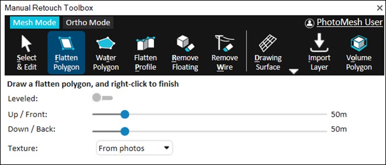
§ Flatten polygon – Remove all elements inside a defined volume, and add a flat surface in the area of the 2D polygon, for e.g., filling holes and flattening walls. The area of the 2D polygon can be textured with any of the following:
§ From photos – Fill the polygon area using photos from the area.
§ Remove moving cars – Fill the polygon area using only photos from the area that don’t include moving cars. This option offers a solution to undesirable reconstruction effects that can occur when capturing an area with moving cars (e.g., a car that is partially sunk in the road), since only some of the captured photos included the cars, while others did not. It is recommended to individually retouch each car you want to remove by applying a unique polygon to it.
§ Single color – Fill the polygon area using a single color.
§ Texture pattern – Fill the polygon area with a water or grass texture.
§ Flatten profile– Create multiple flatten polygons by defining a profile line (usually on a roof top) and the base elevation. A flatten polygon is created for each segment of the profile line (from the line to the base elevation). This method is useful for creating retouch polygons in hard to access places, e.g., between buildings.
§ Remove floating – Remove all elements inside a defined volume. This option is generally used to remove floating elements that aren’t connected to the ground.
§ Remove wire – Remove thin elements such as power lines by drawing a polyline that marks the wire to be removed. A separate floating polygon is created for each segment of the polyline.
To perform a retouch operation in Mesh mode:
1. Select one of the retouch operations in the Manual Retouch Toolbox, and then do the following:
§ Flatten polygon (Shortcut key: f)
i. Switch Leveled on to set the altitude of all polygon points to that of the first point.
ii. Set a buffer for the retouch polygon upwards or frontwards and downwards or backwards in the direction of the polygon’s normal by sliding the Up/Front buffer and Down/Back buffer sliders. If a polygon’s elevation angle to the ground is less than 20 degrees, the polygon is extruded vertically. If the polygon points were created in a clockwise orientation, then the front is the side facing the user.
iii. Select one of the Texture options: From photos, Remove moving cars, Single color, or Texture pattern.
iv. For Single color fill, select the color to use. For Texture pattern fill, select a Texture pattern, and enter a value for the texture tile size.
v. Draw a polygon around the area for flattening. Right-click to complete.
§ Flatten profile(Shortcut key: p)
i. Set a buffer for the retouch polygon upwards or frontwards and downwards or backwards in the direction of the polygon’s normal by sliding the Up/Front buffer and Down/Back buffer sliders. If a polyline's elevation angle to the ground is less than 20 degrees, the polyline is extruded vertically. If the polyline's points were created in a clockwise orientation, then the front is the side facing the user.
ii. Draw the profile line, and then right-click to complete. Then click on the model to define the model's base elevation. A flatten polygon is created for each segment of the profile line (from the line to the base elevation).
§ Remove floating (Shortcut key: r)
i. Click any point on the floating artifact. PhotoMesh automatically creates a polygon that includes the selected point.
ii. Set a buffer for the retouch polygon upwards or frontwards and downwards or backwards in the direction of the polygon’s normal by sliding the Up/Front buffer and Down/Back buffer sliders. If a polygon’s elevation angle to the ground is less than 20 degrees, the polygon is extruded vertically. If the polygon points were created in a clockwise orientation, then the front is the side facing the user.
§ Remove wire (Shortcut key: w)
i. Set a buffer for the retouch polyline upwards or frontwards and downwards or backwards in the direction of the polyline’s normal by sliding the Front buffer and Back buffer sliders. If a polyline's elevation angle to the ground is less than 20 degrees, the polyline is extruded vertically. If the polyline points were created in a clockwise orientation, then the front is the side facing the user.
ii. Draw a polyline along the wire to remove, and then right-click to complete.
2. To select the polygon/polyline for editing after it is drawn, click Select and Edit (Shortcut key: s), and then select the retouch object for editing or right-click it in the Manual Retouch list, and select Edit. When editing a drawn polyline and changing the extrusion length, only the selected line segment is modified. See "Editing Polylines and Polygons" in this chapter for information.
3. To select how to display all manual retouch polygons, click the Volume icon (Shortcut key: o):
§ Volume Colorize – Mark the area for retouching by colorizing all parts of the mesh contained within the extruded polygon.
§ Volume Polygon – Mark the area for retouching by displaying 3D polygons based on the extruded polygon.
§ Volume No – Mark the area for retouching only with a 2D polygon.
Creating Water Body Polygons
The Manual Retouch tool also supports the creation of water bodies. Water bodies are difficult to model accurately because it is hard to identify and match features due to the uniformity and non-static nature of water. In order to enable PhotoMesh to model and texture a water body successfully, you can define the required water body by drawing or importing a corresponding polygon. PhotoMesh uses this polygon to generate a flat surface over the user-defined water body, and automatically reconstruct any above-water elements – boats, piers, small islands without requiring special user markings.
To create a water body polygon:
1. In the Manual Retouch Toolbox, click Water Polygon.
2. Select a Water Type.
§ Smart Water – Detects and flattens water surfaces by analyzing texture colors within the drawn polygon. Even a rough outline is often sufficient. Smart Water also identifies and preserves above-water features such as boats and bridges. To apply this process, PhotoMesh downgrades the affected tiles back to the Point Cloud phase. The polygon must be drawn at an elevation as close as possible to the actual water surface. If the elevation is inaccurate, too high or too low, the water detection may fail or produce incorrect results.
§ Flat Water – Begins with the Smart Water detection process but then overrides the entire polygon area, flattening it completely, regardless of whether water was detected. This ensures a uniform, artifact-free surface, even in areas where water detection may have failed.
3. Set the Leveled switch:
§ On (Leveled) – A constant water level (i.e., altitude) is set for all points in the water body polygon, to create level water bodies such as seas, lakes, ponds, and pools. This is especially useful for creating a level water body on top of a non-flat terrain or mesh, or for creating a flat water body based on an imported polygon with variable altitude values.
§ Off (Sloped) – PhotoMesh segments the water body polygon into multiple flat reconstruction tiles, each of which has a different elevation value based on the average elevation within the specific tile. This option should be selected to create an elevation gradient for water bodies such as rivers, with non-uniform water levels.
4. If you selected Flat Water for the Water Type, set a buffer for the retouch polygon upwards or frontwards and downwards or backwards in the direction of the polygon’s normal by sliding the Up/Front buffer and Down/Back buffer sliders. If a polygon’s elevation angle to the ground is less than 20 degrees, the polygon is extruded vertically. If the polygon points were created in a clockwise orientation, then the front is the side facing the user.
5. With the cursor in the 3D Window, click to add the first point of the polygon. Click again to add additional points of the polygon until you have marked the entire shape. You must place at least three points to define the polygon.
Note: It is sometimes easier to draw an accurate water polygon over a textured mesh model. After adding the model, rebuild, setting the Build Start From field to Auto, so that the required steps are automatically selected.
Note: When creating a water body polygon, the lines of the polygon should not overlap each other.
Note: It is recommended to keep the number of polygon points to the minimum required to define the shape. Adding unnecessary points may adversely affect performance.
6. Right-click to finish the polygon. The polygon name and water average elevation can be modified in the Manual Retouch list. See "Modifying Retouch Objects" in this chapter for information.
7. Click any water polygon in the 3D Window to open the Manual Retouch toolbox showing the following buttons:
§ ![]() Leveled – Assigns a constant water level (altitude) to the entire water body polygon. This option is ideal for creating level water bodies such as seas, lakes, ponds, and pools, especially when the underlying terrain or mesh is uneven. It is also useful when working with an imported polygon whose vertices have inconsistent altitude values. All polygon points are automatically set to the altitude of the first point defined.
Leveled – Assigns a constant water level (altitude) to the entire water body polygon. This option is ideal for creating level water bodies such as seas, lakes, ponds, and pools, especially when the underlying terrain or mesh is uneven. It is also useful when working with an imported polygon whose vertices have inconsistent altitude values. All polygon points are automatically set to the altitude of the first point defined.
§ ![]() Edit Geometry – Opens the polygon’s property sheet and places the polygon in Edit mode, allowing you to modify the polygon’s geometry, including moving, adding, or removing waypoints.
Edit Geometry – Opens the polygon’s property sheet and places the polygon in Edit mode, allowing you to modify the polygon’s geometry, including moving, adding, or removing waypoints.
§
Working in Orthophoto Mode
The following retouch operations are available in Ortho mode:
§ Clean Cars – Remove all elements inside a defined area, and texture the drawn polygon area using only photos from the area that don’t include moving cars. This option offers a solution to undesirable effects in the reconstruction (e.g., a car that is partially sunk in the road) that can occur when capturing an area with moving cars, since only some of the captured photos included the cars, while others did not. It is recommended to individually retouch each car you want to remove by applying a unique polygon to it.
§ Clean Edges – Remove artifacts along the edges of a model.
§ Import Layer – Import a polyline or polygon feature layer with retouch polylines/polygons for cleaning edges or cars. The following layer formats are supported: .shp, sqlite, and gpkg.
To perform a retouch operation in Ortho mode:
1. Select one of the retouch operations in the Manual Retouch Toolbox, and then do the following:
§ Clean Cars (Shortcut key: c)
i. Draw a polygon around the area that you want to clean.
ii. Right-click to complete. The buffers are automatically set to 10 meters above/below the surface.
§ Clean Edges (Shortcut key: e)
i. Set a buffer for the retouch polygon upwards or frontwards and downwards or backwards in the direction of the polygon’s normal by sliding the Up/Front buffer and Down/Back buffer sliders. If a polygon’s elevation angle to the ground is less than 20 degrees, the polygon is extruded vertically. If the polygon points were created in a clockwise orientation, then the front is the side facing the user.
ii. Draw a polyline along the edge you want to clean. Right-click to complete. A polygon is generated with the base line on the ortho surface and the top line, one meter above the surface. All artifacts with a normal vertical to the polygon are cleaned.
§ Import Layer (Shortcut key: i) – See “Importing Retouch and Water Polygons/Polylines” in this chapter for information.
2. To select how to display the drawn polygon, click the Volume icon (Shortcut key: o):
§ Volume Colorize – Mark the area for retouching by colorizing all parts of the mesh contained within the extruded polygon.
§ Volume Polygon – Mark the area for retouching by displaying 3D polygons based on the extruded polygon.
§ Volume No – Mark the area for retouching only with a 2D polygon.
3. To adjust the length to extrude the retouch polygon upwards or frontwards and downwards or backwards in the direction of the polygon’s normal, select the polygon and in the Manual Retouch Toolbox, slide the Front buffer and Back buffer sliders. If a polygon’s elevation angle to the ground is less than 20 degrees, the polygon is extruded vertically. If the polygon points were created in a clockwise orientation, then the front is the side facing the user.
4. To select the polygon for editing after it is drawn, click Select and Edit (Shortcut key: s), and then select the retouch object for editing. Use the mini toolbar to edit the polygon. See "Editing Polylines and Polygons" in this chapter for information. You can also view and edit the manual retouch object’s properties in the Manual Retouch list. See "Modifying Retouch Objects" in this chapter for information.
Importing Polygon and Polyline Feature Layers for Retouching
Polygon and polyline layers created in external software can be imported in both Mesh and Orthophoto modes and automatically converted to retouch elements. Supported formats include SHP, SQLite, and GPKG.
Note: Only external polygon/polyline feature layers can be imported using the method described below. Retouch polygon/polyline layers that were created in PhotoMesh and exported must be reimported using the Import command in the Manual Retouch list. See “Exporting and Reimporting Retouch and Water Polygons” in this chapter for information.
To import a layer with polygons/polylines for retouching:
1. In the Manual Retouch Toolbox, click Import Layer, and then Browse.
2. Browse to the required layer and click Import. The following layer formats are supported: .shp, sqlite, and gpkg. Then click Next.
3. Set the imported layer’s coordinate system. Then click Next.
4. In Mesh mode, if a polygon layer was selected, do the following:
a. Select the Retouch Operation to perform using the imported polygons:
Note: In Ortho mode and for polylines in both modes, the Retouch Operation is always Convert to profile, which converts the imported features to “flatten profiles” with a default vertical distance of one meter.
· Smart Water – Detects and flattens water surfaces by analyzing texture colors within the layer’s polygons. Even rough outlines are often sufficient. Smart Water also identifies and preserves above-water features such as boats and bridges.
· Flat Water – Performs the Smart Water detection process and then flattens the entire polygon area, regardless of whether water was detected. This ensures a uniform, artifact-free surface, even in areas where water detection may have failed.
· Flatten Polygon - Removes all elements inside each polygon, and replaces it with a flat surface based on the polygon’s footprint. Useful for filling holes and flattening walls. The polygon area is textured using photos from the area.
· Remove Moving Cars - Similar to Flatten Polygon, but textures the area using only photos that do not contain moving vehicles. This option is effective only if such photos exist; if all available photos contain moving cars, the results may be incomplete or inaccurate.
· Convert Polygon to Profile – Creates a flatten profile for each segment of each polygon in the layer.
b. Select the elevation behavior of the imported polygons:
· Leveled – A constant level (i.e., altitude) is set for all points in the polygon.
· Non-Leveled (Sloped) – PhotoMesh segments the polygon into multiple flat reconstruction tiles, each of which has a different elevation value based on the average elevation within the specific tile.
5. Switch on Intersect with project to import only polygons or polylines inside the project (AT) area. The retouch polygons included in the layer are added to the Manual Retouch list with a default front and back buffer of 200 meters.
Navigating to and Modifying Retouch Objects
All retouch operations can be viewed and edited from the Manual Retouch list. See "Selecting Items Using the Item List" in the "Basic Concepts" chapter for more information.
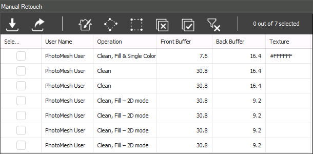
Manual Retouch List
To modify a retouch operation:
1. In the Project Panel, select the Manual Retouch group, and then in the Manual Retouch list, select the row with the required retouch object.
2. Perform any of the following actions:
§ Fly To/Jump To – Right-click the required row, and select Fly To/Jump To.
§ Delete Polygon – Right-click the required row, and select Delete.
§ Edit Polygon – Right-click the required row, and select Edit. The retouch polygon is selected in the 3D Window and a mini toolbar is displayed. See "Editing Polylines and Polygons" in this chapter for information on modifying the polygon shape/position and properties. You can also modify the buffer in the Manual Retouch list.
Exporting and Reimporting Retouch Polygons/Polylines
Retouch and water polygons/polylines created in PhotoMesh can be exported to an SQLite file, modified externally (e.g., in TerraExplorer) and then reimported to PhotoMesh.
Note: The steps below apply only to retouch polygon/polyline layers that were created in PhotoMesh and exported. External feature layers can only be imported using the Import command in the Manual Retouch toolbox or PhotoMesh ribbon. See “Importing Polygon and Polyline Feature Layers” in this chapter for information.
To export retouch and water polygons/polylines:
1. In the Project Panel, select the Manual Retouch group, and then in the Manual Retouch list, select the retouch and water objects that you want to export, and click Export ![]() .. The Export Manual Retouch Objects dialog is displayed.
.. The Export Manual Retouch Objects dialog is displayed.
Note: This action can also be performed from the ribbon command: Home tab > Retouch > Import Manual Retouch:
2. Browse to the location where you want to save the layer, and click Save. The layer is exported with the selected retouch and water objects as an SQLite file.
3. Browse to the required folder, and click Save.
To reimport retouch and water polygons:
1. In the Project Panel, select the Manual Retouch group, and then in the Manual Retouch list, click Import ![]() . The Import Manual Retouch Objects dialog is displayed.
. The Import Manual Retouch Objects dialog is displayed.
2. Browse to the location of the layer, and click Open. The layer is imported as an SQLite file that contains the selected retouch and water polygons.
Setting Retouch Object Properties
Retouch and water body object data (e.g., average elevation and elevation offset) can be viewed or modified in the Manual Retouch list. See "About the Item List" in the "Basic Concepts" chapter for information on working with the Manual Retouch list.
To display and modify water body polygon properties:
1. In the Project Panel, select the Manual Retouch group.
2. In the Manual Retouch list, select the row of the required polygon, and then click in the required column, and modify its properties as required. See "Manual Retouch List" in this chapter for more information.
Note: You can also search the list for the required polygons. See "Selecting Items Using the Item List" in the "Basic Concepts" chapter for information.
Manual Retouch List
In the Manual Retouch list, you can view and set certain manual retouch and water polygon properties, as well as set polygon visibility and inclusion in the project. See "About the Item List" in the "Basi Concepts" chapter for information on working with the manual retouch list.
|
Property |
Description |
|
Selection |
Select the check box to select the polygon for editing. You can select multiple polygons to perform actions on multiple polygons. |
|
User Name |
|
|
Operation |
|
|
Front Buffer |
|
|
Back Buffer |
|
|
Texture |
|
|
Exclude |
Select the check box to exclude the polygon from the project. The polygon continues to display in the 3D Window. |
|
Layer |
Name of the manual retouch layer. |
|
Projection |
|