Setting PhotoMesh Options
Default system settings for the current PhotoMesh project and all future projects are set from the Options dialog.
To modify PhotoMesh Options:
1. From the File menu, select Options (F9). Then select one of the following from the menu in the left pane:
§ Project – Show properties related to the current project
§ Preferences – Default values for the current project and new projects
§ AT Area & Tiles – AT/Reconstruction tiles
§ View – View options
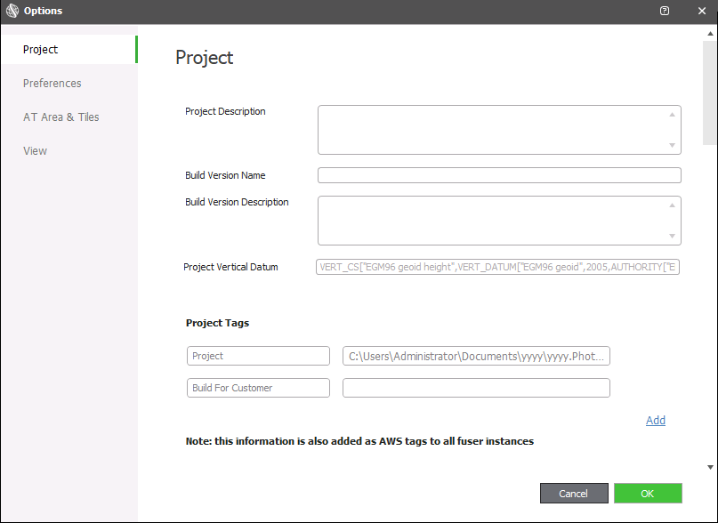
Options Dialog
2. Modify the following settings as required:
|
Parameter |
Description |
|
Note: Project settings only apply to the current project. |
|
|
Project Description |
Free text describing the build. This field is initially populated with the description from the previous build. |
|
Build Version Name |
Name of the build version. This field is initially populated with the name of the previous build. |
|
Build Version Description |
Free text describing the build version. |
|
Project Vertical Datum |
Vertical datum for the current project (Read-only). Note: The Output Vertical Datum field below is only applied to future projects. It is not applied to the currently open project. |
|
Project Tags |
Key words or terms (and their values) associated with the project file for advanced searches. There are two built in tags: "Project Name" with the path to the project file, and "Build For Customer" for information about the project customer. Tags can help you identify the fuser instance in the Amazon EC2 console after it is launched. Click Add to add more tags. |
|
Note: All properties in the Preferences section are applied to the current project and future projects. |
|
|
Working Folder |
The working folder that PhotoMesh Build Manager (on the master computer) and PhotoMesh fusers use to communicate: to deposit and collect pending tasks, and share information about fuser availability, status and progress. The working folder should be set to a network folder with read-write access permissions, for both the master and client computers. See "Setting the Working Folder (on the Master Computer)" in the "Fusers" chapter for information. Click Browse to browse to a different working folder, and then click Select Folder. |
|
Preset Manager |
Click Open to open the Preset Manager to load or manage preset files. See "Working with Presets" in the "Building" chapter for information. |
|
|
Well-Known Text of the output’s vertical datum. By default, this is set to EGM96. Note: You can use the Coordinate System Generator to generate a WKT string defining the required coordinate system. Only enter the Vert_CS entity of the WKT in this field. See "Coordinate System" in the "Basic Concepts" chapter for information. Select Auto to automatically set the output vertical datum based on the first one of the following that has a defined vertical datum: 1. Ground control points. 2. LiDARs 3. Photo collections. If none of these include a vertical datum, the output vertical datum is set to the default EGM96. |
|
Maximum Local Fusers |
Maximum number of local fusers to run. Select Auto to automatically set the number of local fusers based on the amount of memory on the machine and its processing power. See "Launching Multiple Fusers" in this chapter for more information. |
|
DJI Altitude |
Select the DJI altitude information to read from the metadata encoded in the photo files: § Load Absolute – Load the absolute altitude values. § Load Relative – Load the relative altitude values, and define altitude offset based on the terrain elevation at the position of the first photo in each collection. |
|
Load Multispectral Bands |
Select the check box to load multispectral bands for photos. |
|
Terrain Database |
Default MPT (local or remote) or .FLY to use as the base project when creating new project. Click Browse to browse to a different terrain database, and then click Open. Note: If a project is open, changes to the terrain database will take effect only after saving the project file and reopening it. |
|
Terrain Vertical Datum |
Well-Known Text of vertical datum of terrain database. Note: You can use the Coordinate System Generator to generate a WKT string defining the required coordinate system. Only enter the Vert_CS entity of the WKT in this field. See "Coordinate System" in the "Basic Concepts" chapter for information. |
|
Set AT area to include |
PhotoMesh can automatically calculate the AT area based on all the project’s photos plus a buffer. The automatic AT area’s buffer can be based on the collections’ largest effective range, i.e., the maximum distance from the camera for which photo information is considered valid for aerotriangulation, or on a buffer you set. Select one of the following options: § Photo collections' effective range - Calculate the AT area based on the positions of all the project’s photos plus a buffer that is based on the collections’ largest effective range. § Use buffer of - Calculate the AT area based on the positions of all the project’s photos plus the buffer that you set. |
|
Tile Bottom Buffer |
When splitting photos into AT tiles, photos whose frustum intersects with a box that defines the AT tile are included in the tile. This box’s base is defined by the AT area's minimum terrain elevation minus the Tile Bottom Buffer value (in meters). |
|
Tile Top Buffer |
When splitting photos into AT tiles, photos whose frustum intersects with a box that defines the AT tile are included in the tile. This box’s top is defined by the AT area's maximum terrain elevation plus the Tile Top Buffer value (in meters). |
|
Maximum Photos Per Tile |
Maximum number of photos that can be included in an AT tile, even if the Do Not Split If Sum Exceed or Do Not Split If Child Exceed properties (below) are met. When the Maximum Photos Per Tile is reached, tiles are only split if the Do Not Split If Sum Exceed and Do Not Split If Child Exceed properties (below) are both met. Note: When a tile is split, some photos will be included in both sub-tiles, based on frustum area. |
|
Do Not Split If Sum Exceed |
In cases where splitting a tile into sub-tiles, based on Maximum Photos Per Tile, results in a significant number of photos that are included in both tiles, it may not be desirable to split the tile. This property sets the maximum percent the sum of the photos in the sub-tiles can exceed the photos in the original tile. If the percent increase exceeds this value, the tile will not be split into sub-tiles even though Maximum Photos Per Tile was exceeded. |
|
Do Not Split If Child Exceed |
In cases where splitting a tile into sub-tiles, based on Maximum Photos Per Tile, results in sub-tiles that are nearly as large as the original tile, i.e., a significant number of photos were included in both tiles, it may not be desirable to split the tile. This property sets the maximum percentage (of the original tile) for either sub-tile after the split. If either of the sub-tiles exceeds this value, the tile will not be split into sub-tiles even though Maximum Photos Per Tile was exceeded. |
|
Photo Frustum Buffer |
When splitting photos into AT tiles, photos whose frustum volume intersects with a box that defines the AT tile are included in the tile. This property lets you increase or decrease the frustum volume by a set percent. |
|
Fully Trusted Max GP |
Maximum number of gigapixels per AT tile for fully trusted input data when aerotriangulation is not performed. See "Importing Photos with Metadata" in the "Photo Management" chapter for more information on fully trusted data. |
|
Point Cloud Point Size |
Enter the maximum size, in pixels, to display each point. |
|
Show Legend in Review Mode |
Select the check box to display AT Tile and Reconstruction Tile legends in the 3D Window when in review mode, which indicate what color is associated with each AT and Build status. |
|
Original Position |
The camera symbol’s color for photos in the original position. Click Change to select a different color, and then select the color. |
|
Calculated Position |
The camera symbol’s color for photos in the calculated position. Click Change to select a different color, and then select the color. |
|
Failed to Calculate |
The camera symbol’s color for photos whose position PhotoMesh was unable to calculate. Click Change to select a different color, and then select the color. |
|
Excluded |
The camera symbol’s color for photos manually excluded by the user or outside the project crop area. Click Change to select a different color, and then select the color. |
|
AT Tile |
Select the name and color to represent each of the user status options in the AT Tiles list. The user status indicates what actions still need to be performed on the tile, e.g., rebuild or control points. See "Selecting Tiles" and "Viewing Tile Information in the Tile List" in the "Reviewing Your Build" chapter for information. |
|
Reconstruction Tile |
Select the name and color to represent each of the user status options in the Reconstruction Tiles list. The user status indicates what actions still need to be performed on the tile, e.g., rebuild, editing or external retouch. See "Selecting Tiles" and "Viewing Tile Information in the Tile List" in the "Reviewing Your Build" chapter for information. |