Setting the AT (Aerotriangulation) Area
Setting the AT area defines the area of the project on which PhotoMesh should perform aerotriangulation. Aerotriangulation is the process for determining the correct position and orientation of each of the project photos, based on inputted photo information, ground control points and tie points. If a project’s photos do not have fully trusted camera positioning and orientation information, this process must be performed before generation of the 3D mesh model. PhotoMesh uses the highest-performance photogrammetry, computer vision, and computational geometry algorithms in performing aerotriangulation.
The defined AT area can include all the project’s photos or be restricted to only the photos within a specific area on the terrain. This enables you to perform aerotriangulation on a small subset of the project to validate camera parameters and build settings and check the resulting AT and reconstruction tiles before building the full project. The area for the aerotriangulation can be defined by either drawing or importing an AT polygon.
If project photos have no positioning information, you should manually set an initial AT area based on an estimation of the geographical area of the project, which will then be adjusted by PhotoMesh in the aerotriangulation step.
There are two indicators in the 3D Window that photos are outside the current aerotriangulation area:
§ When photos are "colored by status" (See "Selecting Camera Symbol Size and Color" in this chapter), the camera symbols for these photos will be colored in grey.
§ When "Do not show excluded" is selected (See "Displaying Camera Symbols" in this chapter), the camera symbols for these photos are not displayed.
Note: Photos that are outside the currently defined AT area are still considered part of the project and therefore the Exclude check box remains cleared in the photo list.
Setting the AT Area to Include All Photos
The AT area can be calculated automatically based on all the project’s photos plus a buffer. This buffer is defined either by the collections' effective range—representing the furthest distance from the camera at which the photo data remains reliable for aerotriangulation—or by a buffer value that you specify.
To set the AT area to include all the project’s photos:
1. On the Home tab, in the Area group, click the arrow under AT Area and select Change Automatic Setting. The Automatic Area Setting dialog is displayed.
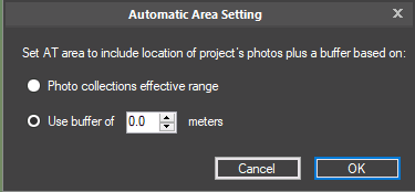
Automatic Area Setting Dialog
2. Select one of the following options:
§ Photo Collections' Effective Range - Calculate the AT area based on the positions of all the project’s photos plus a buffer that is based on the collections’ effective range.
§ Use Buffer of - Calculate the AT area based on the positions of all the project’s photos plus the buffer that you set.
3. On the Home tab, in the Area group, click the arrow under AT Area and select Automatic Using Effective Range/Automatic Using Buffer. The option that is displayed corresponds to the option selected in step 2.
Drawing a New AT Area
To set an AT area within a specific area of interest, do the following:
Note: An AT Area polygon can only be redrawn when Review mode is off. See "About Reviewing Your Build" in the "Reviewing Your Build" chapter for more information about Review mode.
1. On the Home tab, in the Area group, click the arrow under AT Area and select Redraw AT Area.
2. In the 3D Window, draw an AT Area polygon around the required area by clicking in the required locations. You must place at least three points. Right-click to finish the polygon creation.
Importing an AT Area Polygon
To import an AT area polygon;
1. On the Home tab, in the Area group, click the arrow under AT Area, and select Import. The Import Aerotriangulation Area Polygon Layer dialog is displayed.
2. Browse to the shapefile with the required polygon, and click Open.
Note: The first polygon found in the file is used as the aerotriangulation area polygon.
Editing an AT Area Polygon
To edit the current AT area:
Note: An AT Area polygon can only be edited when Review mode is off. See "About Reviewing Your Build" in the "Reviewing Your Build" chapter for more information about Review mode.
1. On the Home tab, in the Area group, click the arrow under AT Area and select Edit AT Area.
2. In the 3D Window, place the cursor over one of the nodes of the AT Area polygon. The node turns blue, and the cursor changes to Move mode ![]() .
.
3. Click the node and drag it to the required location.
4. Release the mouse button to set the node at the current location.
5. Red dots on the polygon’s line segments indicate where a node can be added. Click to add a node, and then drag it to the required location.
6. Right-click to finish editing the polygon.
Navigating to the AT Area
To fly or jump to the AT area:
§ On the Home tab, in the Area group, click the arrow under AT Area and select Fly to Area/Jump to Area.