Using Analysis Tools
The Tools tab provides you with a set of TerraExplorer analysis tools that help you validate photo parameters.
|
Tool |
Description |
|
Displays the aerial distance, elevation difference, horizontal distance and slope angle between two or more points in the 3D Window. |
|
|
Measure the following for a defined area on the terrain: § Horizontal plane – Displays the measurement of the horizontal projection of an area in the 3D Window. § Terrain surface – Displays the measurement of the marked area while taking into account terrain contours. |
|
|
Provides data about any point or object in the 3D World. |
|
|
Enables you to compare two layers or a layer against the base terrain by horizontally swiping between them, dynamically revealing and concealing portions of each. |
Distance Tool
The Distance tool allows you to measure the aerial distance, elevation difference and slope between two or more points. The aerial distance is the actual distance between the points.
To use the Distance tool:
1. On the Tools tab, in the Measure group, click Distance. The Distance Measurement dialog is displayed with the following options regarding display of distance information in the 3D Window:
Note: The aerial, horizontal, and vertical distance information are calculated and displayed in the Distance Measurement dialog even if the respective option was not selected
§ Show Aerial Distance – Show a yellow line marking the aerial distance, i.e., the actual distance between points, in the 3D Window.
§ Show Horizontal Distance – Show a white line marking the horizontal distance between points in the 3D Window.
§ Show Vertical Distance – Show a purple line marking the vertical distance between points in the 3D Window.
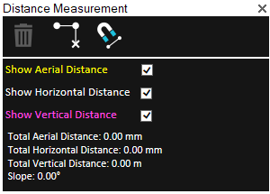
Distance Measurement Dialog
2. If you want to snap the measurement points to an object’s edge or vertex, click Snap ![]() . All edges, i.e., intersections of two plane faces, and vertices, i.e. intersections of two polylines are automatically detected.
. All edges, i.e., intersections of two plane faces, and vertices, i.e. intersections of two polylines are automatically detected.
3. In the 3D Window, click any point on the terrain or on an object to define the start point of the measurement. A yellow line extends from the start point. Drag the cursor to the next point and click again. Repeat to add as many segments as required. If you want to delete the last point added, click Delete Point ![]() . Right-click to finish the measurement.
. Right-click to finish the measurement.
The Distance Measurement dialog displays the following measurements:
|
Measurement |
Description |
|
Total Aerial Distance |
The aerial distance, i.e., the actual distance between the points. This measurement is the sum of the aerial distances between the points as you progress from the start point to the endpoint. |
|
Total Horizontal Distance |
The horizontal distance between the points. This measurement is the sum of the horizontal distances between the points as you progress from the start point to the endpoint. |
|
Total Vertical Distance |
The difference in elevation between the points. If you have marked more than two points, this measurement does not take into account the elevation values of the middle points. |
|
Slope |
The slope of the line between the first and last points. If you have marked more than two points, this measurement does not take into account anything other than the elevation at the start point and the elevation at the endpoint. |
4. If you want to delete the measurement polyline in the 3D Window, click Delete ![]() .
.
5. To perform additional distance measurements, repeat steps 2-3 above.
6. To close this tool, click the X on the top right corner of the dialog.
Area Tool
Using the Area tool, you can calculate area on the terrain or on an arbitrary plane.
To use the Area tool:
1. On the Tools tab, in the Measure group, click Area. The Area Measurement dialog is displayed.
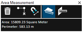
Area Measurement Dialog
2. Click either of the following commands:
§ Horizontal plane area (2D measurement) ![]() - Calculate area on terrain. The area measured is the horizontal projection of the area you have outlined, even if some or all of your selected area encompasses mountainous terrain.
- Calculate area on terrain. The area measured is the horizontal projection of the area you have outlined, even if some or all of your selected area encompasses mountainous terrain.
§ 3D plane area ![]() - Calculate area on an arbitrary plane. The polygon’s orientation is determined by the first three points selected.
- Calculate area on an arbitrary plane. The polygon’s orientation is determined by the first three points selected.
3. If you want to snap the measurement points to an object’s edge or vertex, click Snap ![]() . All edges, i.e., intersections of two plane faces, and vertices, i.e. intersections of two polylines are automatically detected.
. All edges, i.e., intersections of two plane faces, and vertices, i.e. intersections of two polylines are automatically detected.
4. Draw a polygon in the 3D Window that defines the borders of the region being measured:
§ Place the polygon points in the 3D Window by clicking in the desired locations. A red line extends from the start point. If a valid selection area was drawn, the line turns white after the third click, indicating that you can then right-click and obtain the required measurement. A minimum of three points must be selected. If you want to delete the last point added, click Delete Point.
Note: If the boundary line of the measured area crosses itself, it turns red, and a dialog is displayed informing that the polygon is invalid.
5. Right-click to finish the measurement. The Area dialog displays area and perimeter measurements.
6. If you want to delete the area polygon in the 3D Window, click Delete ![]() .
.
7. To perform additional area measurements, repeat steps 2-5 above.
8. To close this tool, click the X on the top right corner of the dialog.
Information Query Tool
The Query tool provides you with data about any point or object in the 3D World. For a point on the terrain, location and elevation information is provided, while for an object, the query also displays the object’s perimeter and area. If the object selected was loaded from a layer with attribute information, the object’s attributes are also displayed.
To use the information query tool:
1. On the Tools tab, in the Measure group, click Query.
2. Move the cursor over any point in the 3D Window. When you move the cursor over an object, the object is highlighted.
3. Click the left mouse button on the point or object for which you require information.
§ In the Message Bar, the longitude, latitude and altitude are displayed.
§ The Query Results dialog is displayed, showing the longitude, latitude, and elevation. When an object is selected, general information about the object and attribute information, if available, is displayed.
4. With the Query tool selected, you can click again on any point in the terrain to find its coordinates. Repeat for as many points as you wish.
On the Tools tab, in the Measure group, click Query again to close the Information Query.
Swipe Mesh, Point Cloud, and Imagery Layers
The Swipe Layers tool enables you to compare two mesh, point cloud, or imagery layers in the same location, or between one of these layer types and the base terrain. Using the tool, you can horizontally swipe between them, dynamically revealing and hiding parts of each layer.
Swipe Layers Tool
To use the Swipe Layers tool:
1. Zoom in on an area with two visible layers, or with a single layer that you want to compare to the base terrain.
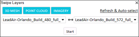
2. On the Tools tab, in the Objects and Layers group, click Swipe Layers. The Swipe Layers controls are displayed.
3. Toggle on/off any of the following: 3D Mesh, Point Cloud, and Imagery to filter the selection to the layer type(s) you want. If you want to refresh the dropdown layers, and automatically detect and select the layers in current view, click Refresh & Auto-Select.
4. Select the layers from the two dropdown lists, and click Start.
5. If comparing mesh model layers, select the mesh model display style:
§ Texture
§ Texture + wireframe
§ Solid color
§ Solid color + wireframe
§ X-ray - Semi-transparent model, enabling you to see through all model walls
6. Slide the slider all the way to the right to completely show the first layer, and all the way to the left to completely show the second one. As the slider moves between these extremes, the first layer is gradually clipped to reveal the second one.
7. Click Auto-Repeat ![]() to automatically loop the slider value between 0-100% to dynamically change the top layer clipping. Click Freeze at any point to freeze the slider at a specific value.
to automatically loop the slider value between 0-100% to dynamically change the top layer clipping. Click Freeze at any point to freeze the slider at a specific value.