Importing and Converting OpenScene Graph (OSGB) Layers
OSGB mesh layers are the native format of the open-source – OpenSceneGraph library http://www.openscenegraph.org/. OSGB layers created in an external application can be imported and converted to the stream optimized, 3DML mesh layer format. See “Uploading Layers to SkylineGlobe Server” in the “Working with SkylineGlobe Server” chapter.
The *.filelist.txt file format is supported for the import and conversion of multiple OSGB tiles into a single 3DML. To use this format, a [FileName].filelist.txt text file should be created that references each of the OSGB tiles to be included in the 3DML. This file must adhere to the following rules:
§ One tile should be referenced per line with the relative path to that tile’s root file in the folder, e.g., ./Tile_485_494/georef/georef.osgb
§ The path is relative to the filelist.txt file
For example, if you have four OSGB tile folders:
§ Tile_485_494
§ Tile_485_495
§ Tile_486_494
§ Tile_486_495
All of these folders should be placed in a directory next to the *.filelist.txt file, and then referenced as follows in the Example.filelist.txt file:
./Tile_485_494/georef/georef.osgb
./Tile_485_495/georef/georef.osgb
./Tile_486_494/georef/georef.osgb
./Tile_486_495/georef/georef.osgb
To import and convert an OSGB mesh layer:
1. On the Layers tab, in the 3D Mesh group, click the arrow next to Load 3D Mesh, and select Import OpenScene Graph Layer.
The Import Mesh and Convert to 3DML dialog is displayed.
2. Browse to the OSGB layer you want to import, and click Open. The Import Mesh and Convert to 3DML dialog is displayed.
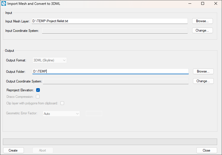
Import Mesh and Convert to 3DML
3. The Input Mesh Layer is automatically populated based on the OSGB layer selected in the previous step.
4. The mesh model’s coordinate system is automatically read from the imported file. If you want to change the model’s coordinate system, in the Input Coordinate System field, click Change. See “Coordinate System Dialog” in the “Basic Concepts” chapter for information.
Note: The coordinate system and model center information can be read from a metadata.xml file that is placed next to the *.filelist.txt file. This is good in the case of non-planar CS models. The metadata.xml can be obtained or generated from PhotoMesh or manually generated. Please attach a sample.
5. Browse to the required Output Folder. The converted mesh model will be saved to this folder.
6. In the Output Coordinate System, set the output mesh model’s coordinate system. This is by default set to the project’s terrain coordinate system. If you want to change the model’s coordinate system, in the Output CS field, click Change. See “Coordinate System Dialog” in the “Basic Concepts” chapter for information.
7. If you want to reproject the input layer’s elevation values to the output coordinate system, select the Reproject Elevation check box.
8. If you want to import sections of the mesh layer using clip polygons on the clipboard, select the Clip layer with polygons from clipboard check box.
Note: Only objects with a polygon geometry, i.e., created via 2D Objects > Polygon (on the Home or Objects tab) or polygons in a feature layer are supported.
9. A correction factor sometimes must be applied to a layer’s geometric error value so that the 3DML will display properly in TerraExplorer. Geometric error together with other properties allow the viewer to determine the optimal balance between quality and performance so that the best Level of Detail (LOD) for the current view can be used. In the Geometric Error Factor field, select Auto to automatically calculate the factor for optimal display in TerraExplorer.
10. Click Create. The created 3DML is added to the project and displayed in the Project Tree.