Scaling and Rotating 3D Mesh Layers
Inaccuracies in mesh layers’ scale, rotation and positioning can be corrected using the Scale and Rotate tool and saved in the mesh layer file. These inaccuracies generally stem from inaccurate positioning hardware.
Note: Scale, rotation, and positioning values can also be modified in the mesh layer’s property sheet. See “Setting and Editing 3D Mesh Layer Properties” in this chapter for more information. When properties are only modified in the property sheet, the mesh layer is only changed in the specific project's Fly file. Changes are saved to the mesh layer itself only if they are made using the Scale and Rotate tool.
To scale, rotate, and reposition a mesh layer:
1. In the Project Tree, select the required layer.
2. On the 3D Mesh Layer tab, in the Mesh Layer group, click Scale and Rotate. The Scale and Rotate dialog box is displayed. with the 3DML already selected in the 3D Mesh Model field.
Note: If you want to change the layer after the tool is open, select the required layer in the Project Tree, and in the tool dialog box, click Capture.
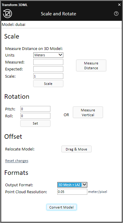
Scale and Rotate Dialog Box
3. Set the required scale: If you know the required scale value, enter it in the Scale field and click Scale. Otherwise, you can set the scale by measuring a specific, generally, easily distinguishable section of the model and calculating the ratio of the expected measurement (based on the real world measurement) to the actual measurement. Do the following:
a. The Units value is automatically populated with the units set for Altitude and Distance in the Options dialog See “View” in “Using TerraExplorer Options” for more information. If you want to use different units, select the required Units.
b. Click Measure on 3D.
c. In the 3D Window, mark the two endpoints of the section of the model that you want to measure, and right click to set the distance value in the Measured field. See “Distance Tool” in the “Analysis Tools” chapter for more information.
d. In the Expected field, enter the actual, real world measurement of this section of the model.
e. Click Calculate to calculate the scale factor and resize the model. The scale factor is calculated based on the ratio between the Expected and Measured values and entered in the Scale field.
4. Set the required rotation: The Pitch and Roll values are populated automatically based on the model’s property sheet. If you know the required Rotation values, enter them. Alternatively, if you have two points on the model that you know should be vertically aligned, e.g., the base and top of a flag pole, you can mark these points, and TerraExplorer can use this information to adjust the pitch and roll so that these points will actually be vertically aligned. Do the following:
a. Click Measure Vertical.
b. On the model, click a point on the bottom and then click a point towards the top that should be directly above the first point. The model’s new pitch and roll are calculated and entered in their respective fields.
c. Click Set to set the model’s rotation according to the new values.
5. Change the model’s position: In the Offset section, do the following:
a. Click Drag & Move. The model’s property sheet is displayed.
b. Modify the layer’s properties in the property sheet or click Move in XY Plane ![]() to drag the model to the required position in the 3D Window. See “Setting and Editing 3D Mesh Layer Properties” in this chapter for more information.
to drag the model to the required position in the 3D Window. See “Setting and Editing 3D Mesh Layer Properties” in this chapter for more information.
6. If you want to reset the dimensions, rotation, or position of the model to the original value, click Reset changes.
7. Select one of the Output Format options:
§ 3D Mesh
§ 3D Mesh and LAS
§ 3D Mesh and LAZ
8. If you selected an output format option including point cloud, set the Point Cloud Resolution in meters/pixel.
9. Click Convert Model. The tool opens the SLMesh Converter command line tool to generate a new mesh layer file with the corrected scale, rotation and location. The new model is created in the same folder as the original model.
10. To view the new model, delete the old version of the model from the Project Tree, and load the new one.