Terrain Profile Tool
The Terrain Profile tool displays the terrain elevation profile along a defined path, and related information on this profile such as maximum and minimum elevation values and slope. The terrain profile can also compare the terrain profile of two layers or of a layer and the base terrain.
To use the Terrain Profile tool:
1. On the Analysis tab, in the Terrain Analysis group, click Terrain Profile. The Terrain Profile dialog is displayed.
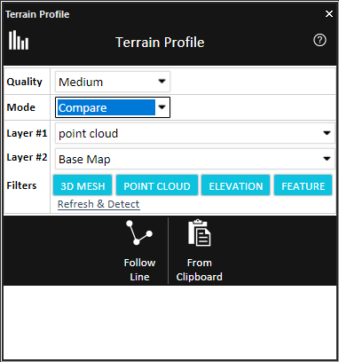
Terrain Profile – Compare Mode
2. Enter the following parameters:
|
Parameter |
Description |
|
Quality |
Determines the distance between sample points along the polyline for which the terrain profile is being calculated. High Quality will yield a more accurate result but take longer to calculate. |
|
Mode |
Select the profile mode. § Normal – Display a profile only for the selected polyline(s). § Compare – Generate terrain profiles for the path defined by the selected polyline for two different layers or for a layer and the base terrain, so that they can be easily compared. |
|
Layer #1 |
Select the first layer for comparison. This property is only available if Compare is selected in the Mode field. Only layers that are calculated as part of the terrain’s elevation (i.e., their “Ground Object” property is set to yes) are included in the dropdown lists. |
|
Layer #2 |
Select the second layer for comparison. If you want to refresh the dropdown layers, and automatically detect and select the layers in current view, click Refresh & Detect. This property is only available if Compare is selected in the Mode field. |
|
Filters |
Toggle on the layer types which you want to include in the layer dropdown lists. |
3. Select one of the following methods of designating the polyline(s) for which the terrain profile should be calculated:
§ Follow Line – A terrain profile is created along the drawn line. In the 3D Window, left-click to place the line waypoints, and right-click to complete the line.
Note: When a terrain profile is created by "Follow Line", a group is created in the Project Tree with the drawn line object.
§ Selected Group – A terrain profile is created for each of the polylines in the selected group. Select the required layer from the Project Tree, and then click Selected Group. This option is only available in Normal mode.
§ From Clipboard – A terrain profile is created for each of the polylines in the clipboard.
A terrain profile graph opens, displaying the terrain elevation profile.
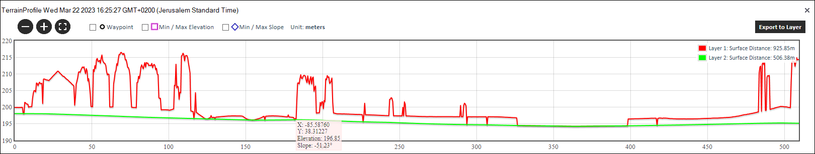
Terrain Profile Graph
4. Use the Zoom in ![]() , Zoom out
, Zoom out ![]() , and Zoom to full extent of data
, and Zoom to full extent of data ![]() buttons to adjust the zoom as required.
buttons to adjust the zoom as required.
5. Determine what information is indicated on the graph by selecting any of the following display options:
|
Waypoint |
Select the check box to mark each of the polylines' waypoints on the graph with a |
|
Min/Max Elevation |
Select the check box to mark each of the polylines' maximum and minimum points with a |
|
Min/Max Slope |
Select the check box to mark each of the polylines' maximum and minimum slope with a |
6. If you want to export the terrain profile to a shapefile layer, click Export to Layer.
Note: When a terrain profile created for multiple lines (in a group or from clipboard), is exported to a layer, the line color on the graph corresponds to the color of the points that make up the line in the layer.
7. Point to any point on the graph to display the following values. If you want to display the values and jump to the point on the terrain, then click instead of pointing.
|
Value |
Description |
|
X |
X-coordinate of the selected point. |
|
Y |
Y-coordinate of the selected point. |
|
Elevation |
Elevation value of the point above the terrain database vertical datum base ellipsoid. |
|
Slope |
Slope of the curve at the selected point |
When comparing between two layers, visibility is turned off for all layers in the area except for the two selected layers so all other layers don’t interfere with the calculations. After the calculations are performed, the original visibility for all the layers is restored.