Viewshed on Route Tool
The Viewshed on Route tools provide you with a graphical representation of the view on the terrain from a series of points (route):
§ 3D Viewshed on Route by Speed – Provides an animated representation of the terrain and objects that are visible as a dynamic object progresses along a defined route according to a set speed.
§ 3D Viewshed on Route by Time – Provides an animated representation of the terrain and objects that are visible as a dynamic object progresses along a defined route over a defined time frame.
§ 3D Viewshed on Route Query– Analyzes the visibility of a selected area from multiple viewshed observer viewpoints along a route.
§ 2D Viewshed on Route - Provides an animated representation of the terrain that is visible as a dynamic object progresses along a defined route
Note: When calculating the viewshed from a route, the field of view is automatically set to 360°.
Creating a 3D Viewshed on Route – By Speed
The 3D viewshed on route – by speed provides an animated representation of the terrain and objects that are visible as a dynamic object progresses along a defined route according to a set speed.
To create a viewshed from a route – by speed:
1. On the Analysis tab, in the Line of Sight group, click the arrow next to Viewshed on Route, and then click 3D Viewshed on Route – By Speed.
The 3D Viewshed on Route property sheet is displayed.
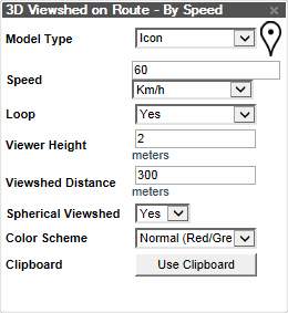
Viewshed on Route – By Speed Dialog
2. In the Viewshed on Route dialog, set the required parameters:
|
Property |
Description |
|
Model Type |
Graphic representation of the dynamic object. Select one of the 3D models: Car, Humvee or Tank, Icon for a 2D image icon, or Empty for no graphic representation. |
|
Speed |
Speed of the dynamic object in mph or km/h. |
|
Loop |
Defines whether the dynamic object stops at the end of the path or loops back to the beginning. |
|
Viewer Height |
Altitude of your viewpoints. |
|
Viewshed Distance |
Distance of the 3D viewshed (in meters). |
|
Spherical Viewshed |
Select Yes to create a full 360 degree sphere. |
|
Color Scheme |
Select the colors that will represent the visible and non-visible areas from the viewshed. |
|
Clipboard |
Viewpoints are created at all clipboard objects. |
3. Once you have set the necessary parameters, click in the 3D Window to define the first waypoint on your route. Drag and click the mouse to define the route’s other waypoints. Right-click to finish. The Dynamic 3D Viewshed group appears in the Project Tree. As the dynamic object moves along the defined route according to the set speed, the viewshed dynamically changes providing an animated representation of the terrain and objects that are visible from each point on the route.
Creating a 3D Viewshed on Route – By Time
The 3D viewshed on route – by time calculates and dynamically marks the terrain and objects that are visible from an object as it moves along a defined route over the course of a set time frame.
To create a viewshed from a route – by time:
1. On the Analysis tab, in the Line of Sight group, click the arrow next to Viewshed on Route, and then click 3D Viewshed on Route – By Time. The 3D Viewshed on Route property sheet is displayed.
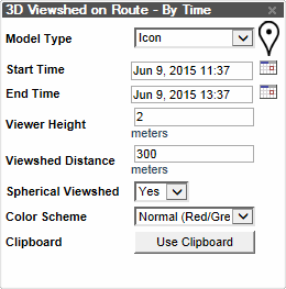
Viewshed on Route – By Time Dialog
2. In the Viewshed on Route dialog, set the required parameters:
|
Property |
Description |
|
Model Type |
Graphic representation of the dynamic object. Select one of the 3D models: Car, Humvee or Tank, Icon for a 2D image icon, or Empty for no graphic representation. |
|
Start Time |
The time the dynamic object begins moving along the defined route. The date and time slider automatically adjusts to correspond to the timespan defined by the Start Time and End Time. |
|
End Time |
The time the dynamic object reaches the end of the defined route. |
|
Viewer Height |
Altitude of your viewpoints. |
|
Viewshed Distance |
Distance of the 3D viewshed (in meters). |
|
Spherical Viewshed |
Select Yes to create a full 360 degree sphere. |
|
Color Scheme |
Select the colors that will represent the visible and non-visible areas from the viewshed. |
|
Clipboard |
Viewpoints are created at all clipboard objects. |
3. Once you have set the necessary parameters, click in the 3D Window to define the first waypoint on your route. Drag and click the mouse to define the route’s other waypoints. Right-click to finish. The created 3D Viewshed on Route group appears in the Project Tree. When the time and date are adjusted in the Time and Date slider and the dynamic object moves along the defined route, the viewshed dynamically changes, providing a representation of the terrain and objects that are visible from each point on the route.
Querying a 3D Viewshed on Route
The Viewshed Query tool enables you to analyze the visibility from multiple viewshed observer viewpoints along a route to a selected area. Based on the 3D viewshed analysis object, the tool computes the overall visibility of different points in the designated area. The output of the analysis is exported to a point shapefile that graphically represents the visibility of the different points. Two color schemes are available; one scheme only distinguishes between visible (green) and invisible (red), while the other one color codes the points according to their visibility percentage:
§ Green = More than 80% of the route’s viewpoints are visible from this point.
§ Yellow = 50 - 80% of the route’s viewpoints are visible from this point.
§ Orange = 0-50% of the route’s viewpoints are visible from this point.
§ Red = 0% of the route’s viewpoints are visible from this point.
To create a 3D viewshed on route – query:
1. On the Analysis tab, in the Line of Sight group, click the arrow next to Viewshed on Route, and then click 3D Viewshed on Route – Query. The 3D Viewshed on Route property sheet is displayed.
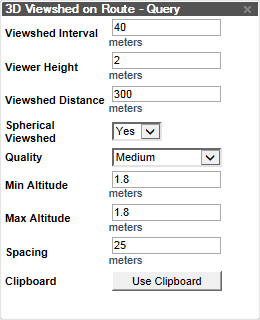
Viewshed on Route – Query Dialog
2. In the Viewshed on Route dialog, set the required parameters:
|
Property |
Description |
|
Viewshed Interval |
The distance between terrain samples for the measurement along each ray. A smaller sample size is more accurate but slower to calculate. |
|
Viewer Height |
Altitude of your viewpoints. |
|
Viewshed Distance |
Distance of the 3D viewshed (in meters). |
|
Spherical Viewshed |
Select Yes to create a full 360 degree sphere. |
|
Quality |
Accuracy level of the viewshed calculation. |
|
Min Altitude |
Defines the altitude above ground level of the closest point to the ground. |
|
Max Altitude |
Defines the maximum altitude above ground level. If the Max Altitude is higher than the Min Altitude, the 3D Viewshed Query tool generates a matrix of points according to the Spacing value. |
|
Spacing |
Determines the horizontal and vertical spacing (in meters) between query points in the area for which the viewshed query is being calculated. The spacing property also defines the scale of the output points. |
|
Clipboard |
Viewpoints are created at all clipboard objects. |
3. Once you have set the necessary parameters, click in the 3D Window to define the first waypoint on your route. Drag and click the mouse to define the route’s other waypoints. Right-click to finish. The output of the analysis is exported to a point feature layer that graphically represents the visibility of the different points.
4. In the 3D Window, click any of the route’s Indicator ![]() icons to toggle display of the viewshed from that individual point.
icons to toggle display of the viewshed from that individual point.
Creating a 2D Viewshed on Route
The 2D Viewshed on Route calculates the terrain that is visible as a dynamic object progresses along a defined route.
There are three options for displaying the calculated route viewshed:
§ Individual viewshed results for each selected point along the route
§ A series of individual viewshed results that display according to a set timespan
§ A single composite viewshed showing visible area from any of the route’s waypoints
Note: When calculating the viewshed from a route, the field of view is automatically set to 360°.
To create a viewshed from a route:
1. On the Analysis tab, in the Line of Sight group, click the arrow next to Viewshed on Route, and then click 2D Viewshed on Route:
The Viewshed on Route property sheet is displayed.
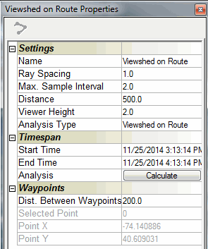
Viewshed on Route Property Sheet
2. In the Viewshed Analysis property sheet, set the required parameters:
|
Property |
Description |
|
Name |
Type the description or name of the viewshed. This text appears in the Project Tree as the name of the object. |
|
Ray Spacing |
Determines the horizontal and vertical spacing (in meters) between each ray (in degrees). The smaller the ray spacing, the more accurate the measurement, but the longer it takes to calculate. |
|
Max. Sample Interval |
The distance between terrain samples for the measurement along each ray. A smaller sample size is more accurate but slower to calculate. |
|
Distance |
Length of the 3D viewshed from the viewer (in meters). |
|
Viewer Height |
Altitude of your viewpoints. |
|
Analysis Type |
Select one of the options for displaying the viewshed: § Viewshed on Route: Individual viewshed results for each selected point along the route. Each circle has a radius equal to the Distance of Sight. § Timespan Viewshed on Route: A series of individual viewshed results that display according to a set timespan § Cumulative Viewshed on Route: A single composite viewshed showing visible area from any of the route’s waypoints |
|
Start Time |
The time the dynamic object begins moving along the defined route. The date and time slider automatically adjusts to correspond to the timespan defined by the Start Time and End Time. |
|
End Time |
The time the dynamic object reaches the end of the defined route. |
|
Dist. Between Waypoints |
Distance between sample route waypoints. |
3. Once you have set the necessary parameters, click in the 3D Window to define the first waypoint on your route. Drag and click the mouse to define the route’s other waypoints. Right-click to finish.
Note: While creating the route, the Dist. Between Waypoints property is still editable.
4. Click Calculate. The created Viewshed on Route locked group appears in the Project Tree.
5. Once you establish the endpoint, all the parameters become read-only. At this point, TerraExplorer Pro begins to calculate the viewshed measurement. This process can take some time if the route has a considerable number of waypoints.