Creating a virtual 3D layer
The Virtual 3D Layer tool combines multiple 3D mesh layers published to SkylineGlobe Server into a single, unified virtual layer. The source layers can come from different datasets, represent different acquisition dates, and/or overlap geographically.
Instead of rebuilding the underlying 3D data, the tool creates a virtual dataset that references the original layers and generates only the connection blocks needed to combine them into one layer. The virtual layer is easily updated by adding or replacing source layers.
For each source layer, you can define a clipping polygon and set draw order. Once configuration is complete, the tool creates and publishes the virtual dataset to SkylineGlobe Server as a single o3DML layer, with standard layer properties and progress feedback provided during the process.
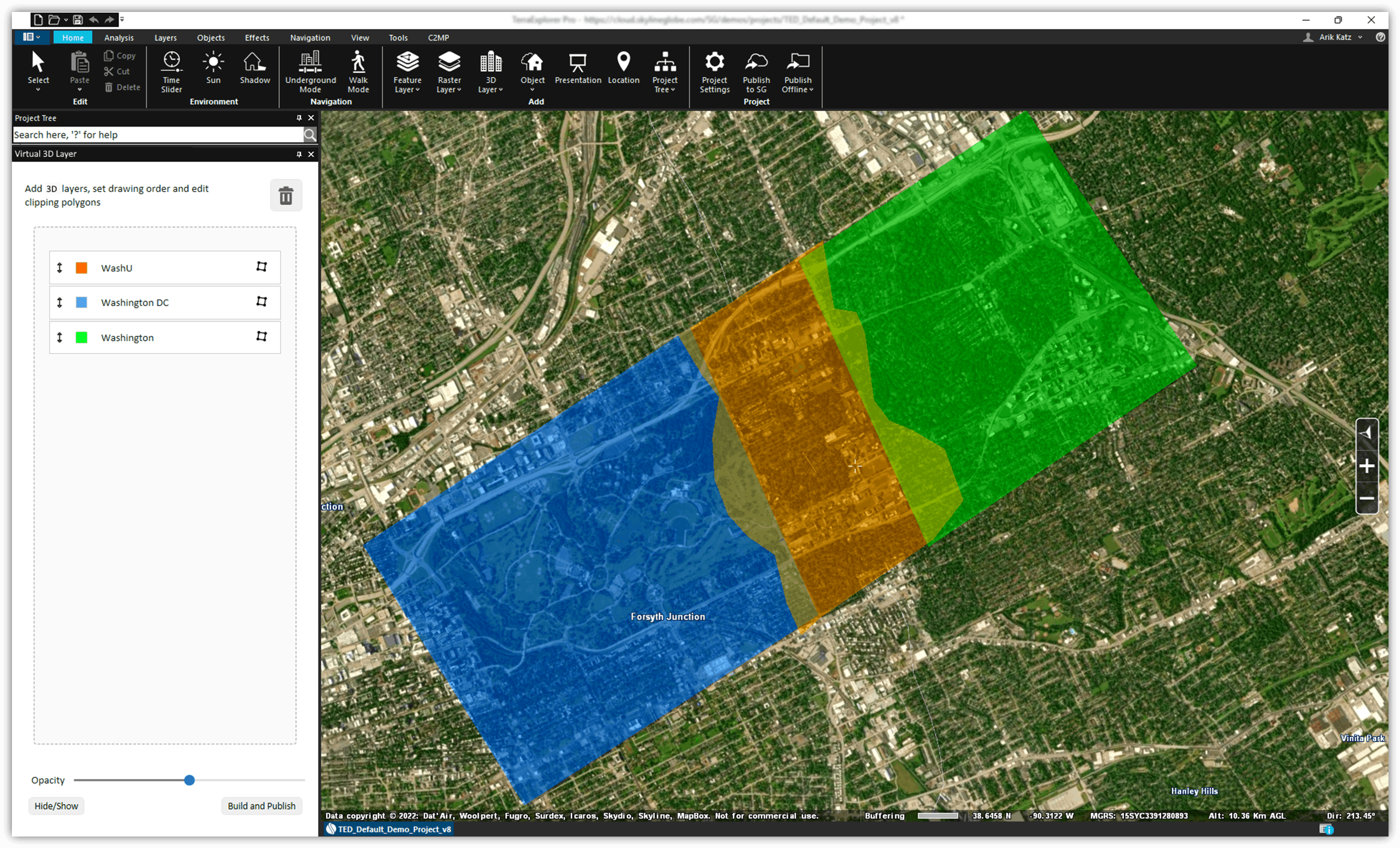
When the Virtual 3D Layer tool is used, TerraExplorer creates a local GeoPackage-based dataset that stores the clipping polygons and other configuration information used to build the virtual layer, and a corresponding configuration feature layer (e.g., Virtual 3D Layers_387), is listed in the Project Tree. If the tool or project is closed, this feature layer can be dragged into the tool to reload the previously defined configuration. The configuration feature layer can be dragged into the tool only when the tool is empty, so it should be added before any mesh layers are loaded.
To create a virtual 3D layer:
1. On the Layers tab, in the 3D Layer group, click Virtual Mesh Layer. The Virtual 3D Layer dialog is displayed.
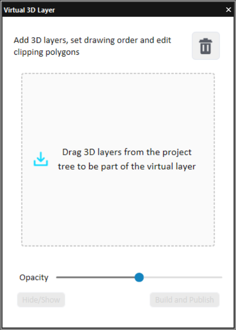
Virtual 3D Layer Dialog
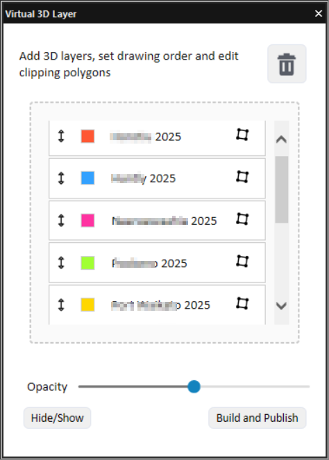
2. Drag one or more online 3D mesh layers from the Project Tree into the tool dialog. When valid mesh layers are dragged in, the container frame turns green; if invalid, it turns red. Each added layer is assigned a unique color displayed in the dialog's layer list and used to colorize the mesh in the 3D Window.
Virtual 3D Layer Dialog
Notes:
§ All source layers must be online layers streamed from the same connected SkylineGlobe Server, to which you have Edit access.
§ You can drag a folder of layers. Only valid layers in the folder are added.
§ If a previously saved virtual layer configuration references layers that are not currently available in the Project Tree, those layers appear as disabled in the layer list.
§ Hidden layers become shown when dragged into the tool.
3. Define the draw order:
§ Drag and drop layers to rearrange them. The topmost layer in the tool has the highest order and appears on top in the 3D view. You can also adjust the order by right-clicking a layer and select Bring to Front or Send to Back.
§ Use the Opacity slider to adjust the transparency of the unique color assigned to each layer.
§ Double-click a layer to fly to its location in the 3D Window.
§ Use the Hide/Show button to toggle visibility of all listed layers in the Project Tree and 3D Window. To show only a specific layer and hide all others (and jump to that layer), right-click the layer and select Show Only.
4. To remove a layer, drag the layer to the trash  icon in the tool dialog. If a layer is deleted from the Project Tree, it is also removed from the virtual layer container and attribute table.
5. To add a clipped version of a mesh layer to the virtual 3D layer, in the Virtual 3D Layer dialog, double-click the layer to zoom out to its fullest extent. Then click Clip Polygon  . The clip polygon is displayed in the 3D Window in Edit mode and an Edit panel is displayed. Do any of the following:
Edit the polygon:
§ Move a node: Click and drag the node, and then release the mouse button to set the node at the current location.
§ Add a node: Place the cursor over one of the red nodes and then click and drag it to the required location.
§ Delete a node: Right-click the node and select Delete Node.
§ Redraw: Click to delete the existing clip polygon and draw a new one.
§ Undo / Redo: Use the buttons in the panel or press Ctrl + Z (Undo) or Ctrl + Y (Redo).
§ Cancel: Exit Edit mode without saving changes. All modifications made since entering Edit Mode are discarded.
Apply the polygon to the 3D mesh:
§ Auto-Apply: Switch on to automatically refresh the clipped 3D mesh after each edit.
§ Apply: When Auto-Apply is switched off, click to apply your edits.
§ Finish: When Auto-Apply is switched off, click to apply your edits and exit Edit mode.
6. Click Build and Publish to proceed to layer setup and publishing. The Virtual 3D Layer properties dialog is displayed.
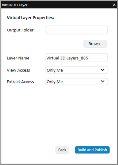
Virtual Layer Properties
7. Set the following:
§ Output Folder – Click Browse and select a temporary location for the o3DML file.
§ Layer Name – Type the virtual layer's name as you want it to appear in SGS.
§ View Access – Set view access (Only Me, My Group, My Site, Everyone).
§ Extract Access - Set extract access (Only Me, My Group, My Site, Everyone).
8. Click Build and Publish. The o3DML file is first built locally. After a successful build, the system proceeds automatically to publishing to SGS. The published virtual layer is a single o3DML layer that references multiple source layers on the same SkylineGlobe Server. The virtual layer can also be exposed as OGC 3D Tiles for use in 3D Tiles–compatible applications.
9. After the publishing process is complete, a dialog is displayed asking if you want to load the layer from SGS. Click Load Layer to load the layer. Click Create New to start creating a new virtual 3D layer.