Measurement tools
The following measurement tools are available:
§ Query
§ Distance
§ Area
Measurements can display dynamically as well as be saved in the Project Tree as TerraExplorer objects.
Information query
The Information Query tool provides you with data about any point or object in the 3D World. For a point on the terrain, location and elevation information is provided, while for an object, the query also displays the object’s perimeter and area. If the object selected was loaded from a layer with attribute information, the object’s attributes are also displayed.
To use the information query tool:
1. On the Analysis tab, in the Measurement group, click Query.
2. Move the cursor over any point in the 3D Window. When you move the cursor over an object, the object is highlighted.
3. Click on the point or object for which you require information.
§ In the Message Bar, TerraExplorer Pro displays the longitude, latitude and altitude.
Note: Military Grid Reference System (MGRS) coordinates are also displayed if Show MGRS Coordinates was selected in the Options dialog. See "View" in the "Using TerraExplorer Options" chapter for more information.
§ The Query Results dialog is displayed, showing the longitude, latitude, and elevation. When an object is selected, general information about the object and attribute information, if available, is displayed.
4. With the Information Query tool selected, you can click again on any point in the terrain to find its coordinates. Repeat for as many points as you wish.
5. On the Analysis tab, in the Measurement group, click Query again to close the Information Query.
Distance tool
The Distance tool measures aerial, horizontal and vertical distance and slope between two or more points. You can also calculate and display the terrain elevation profile for the aerial measurement line.
To use the distance tool:
1. On the Analysis tab, in the Measurement group, click Distance. The Distance Measurement dialog is displayed.
2. In the 3D Window, click any point on the terrain or on an object to define the start point of the measurement. A yellow line extends from the start point. Drag the cursor to the next point and click again. If Multiline is switched off in Settings, the measurement will automatically complete after two points. If Multiline is switched on, you can click to add additional segments, and then right-click to finish. If you want to delete the last point drawn, click Undo ![]() .
.
3. Use the switches in the Distance Settings ![]() panel to turn on/off the display of aerial, horizontal, and vertical distance measurements in the 3D Window. Aerial distances are marked as solid yellow lines, while horizontal and vertical distances are displayed as dashed white lines. See "Distance Settings" in this chapter for information.
panel to turn on/off the display of aerial, horizontal, and vertical distance measurements in the 3D Window. Aerial distances are marked as solid yellow lines, while horizontal and vertical distances are displayed as dashed white lines. See "Distance Settings" in this chapter for information.
Note: While a measurement is in progress, you can stop it and start a new one by clicking Cancel.
4. If you want to calculate an elevation profile for the path defined by the line you drew, in the Distance Measurement panel, click Elevation Profile ![]() . When calculation is complete, an elevation profile graph is displayed, showing the elevation profile.
. When calculation is complete, an elevation profile graph is displayed, showing the elevation profile.
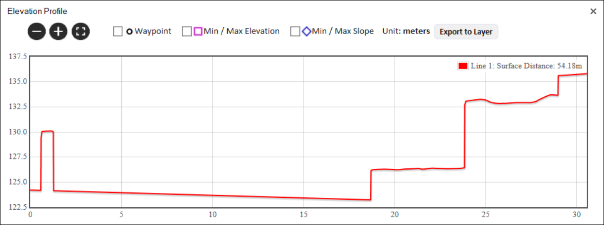
Elevation Profile Graph
a. Use the Zoom in ![]() , Zoom out
, Zoom out ![]() , and Zoom to full extent of data
, and Zoom to full extent of data ![]() buttons to adjust the zoom as required.
buttons to adjust the zoom as required.
b. Determine what information is indicated on the graph by selecting any of the following display options:
|
Waypoint |
Select the check box to mark each of the polylines' waypoints on the graph with a |
|
Min/Max Elevation |
Select the check box to mark each of the polylines' maximum and minimum points with a |
|
Min/Max Slope |
Select the check box to mark each of the polylines' maximum and minimum slope with a |
c. If you want to export the elevation profile to a shapefile layer, click Export to Layer.
d. Point to any point on the graph to display the following values. If you want to display the values and jump to the point on the terrain, then click instead of pointing.
|
Value |
Description |
|
X |
X-coordinate of the selected point. |
|
Y |
Y-coordinate of the selected point. |
|
MGRS |
The coordinates of the selected point converted to Military Grid Reference System (MGRS) coordinates. This field is only available if Show MGRS Coordinates was selected in the Options dialog. See "View" in the "Using TerraExplorer Options" chapter for more information. |
|
Elevation |
Elevation value of the point above the terrain database vertical datum base ellipsoid. |
|
Slope |
Slope of the curve at the selected point |
Distance settings
Distance measurement settings are set in the Distance Settings ![]() panel. These settings are saved on the machine the project is running on, so they are retained for all measurements within the current project and persist between TerraExplorer sessions.
panel. These settings are saved on the machine the project is running on, so they are retained for all measurements within the current project and persist between TerraExplorer sessions.
To set distance measurement settings:
1. On the Analysis tab, in the Measurement group, click Distance. The Distance Measurement dialog is displayed.
2. Click Settings ![]() , and set the following distance options:
, and set the following distance options:
|
Units |
Select either Kilometers/Meters or Miles/Feet. The units will automatically switch to kilometers if the number of meters exceeds 2,000, or to miles if the number of feet exceeds 10,000. See "View" in the "Using TerraExplorer Options" chapter for more information. |
|
Save Measurement |
Select one of the following: § Delete on Exit – Delete the measurement after the Distance tool is closed. § Save in Project – Save the measurement results in the project. |
|
Switch Multiline on to allow measurements of more than two points. When Multiline is switched off, distance measurements automatically complete after the second point is added, eliminating the need to right-click to finish the measurement. |
|
|
Snap Waypoints |
Switch on to enable snapping to object edges or vertices. TerraExplorer automatically detects all edges, i.e., intersections of two plane faces, and vertices, i.e., intersections of two polylines. |
|
Show… |
Use the switches to control the display of aerial, horizontal, and vertical distance measurements in the 3D Window. All measurements are always calculated and listed in the Distance Measurement dialog, regardless of display settings. § If all switches are turned off, the aerial distance switch is automatically re-enabled. § If horizontal and/or vertical measurements are enabled while aerial distance is disabled, the measurement line remains visible but is drawn with a thinner width, and its label is hidden. |
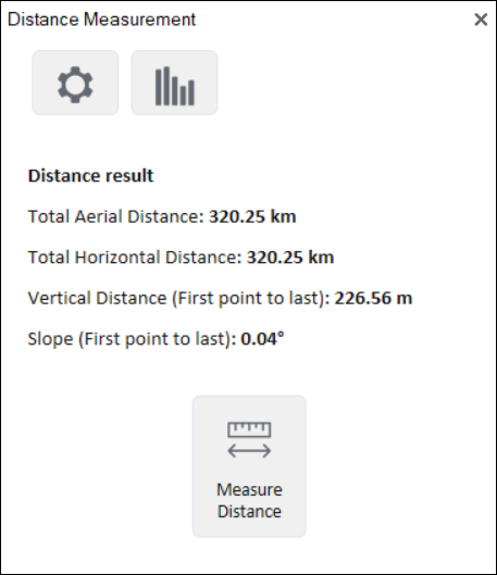
Distance Measurement
The Distance dialog displays the following measurements:
|
Measurement |
Description |
|
Total Aerial Distance |
The aerial distance, i.e., the actual distance between the points. This measurement is the sum of the aerial distances between the points as you progress from the start point to the endpoint. |
|
Total Horizontal Distance |
The horizontal distance between the points. This measurement is the sum of the horizontal distances between the points as you progress from the start point to the endpoint. |
|
Total Vertical Distance |
The difference in elevation between the points. If you have marked more than two points, this measurement does not take into account the elevation values of the middle points. |
|
Slope |
The slope of the line between the first and last points. If you have marked more than two points, this measurement does not take into account anything other than the elevation at the start point and the elevation at the endpoint. |
Area tool
The Area tool allows you to calculate area on the terrain or on an arbitrary plane.
To use the area tool:
1. On the Analysis tab, in the Measurement group, click Area. The Area Measurement dialog is displayed.
2. In the 3D Window, click any point on the terrain/plane to define the start point of the measurement, and then click to set the second point and again for each additional point. Right-click to finish the measurement. If you want to delete the last point drawn, click Undo ![]() . The calculated area and perimeter are displayed in the area measurement panel and in the 3D Window.
. The calculated area and perimeter are displayed in the area measurement panel and in the 3D Window.
Area settings
Area measurement settings are set in the Area Settings panel. These settings are saved on the machine the project is running on, so they are retained for all measurements within the current project and persist between TerraExplorer sessions.
To set area measurement settings:
1. On the Analysis tab, in the Measurement group, click Area. The Area Measurement dialog is displayed.
2. Click Settings ![]() , and set the following measurement options:
, and set the following measurement options:
|
Measurement Type
|
Select one of the following: § Automatic – Automatically determines the projection type based on the normal of the plane formed by the first three points drawn. If the normal's angle is less than 25 degrees (where 0 degrees represents a horizontal surface with a vertically aligned normal), the projection will be horizontal. Otherwise, the tool will create a 3D plane projection based on these three points. § Horizontal Projection – Always calculate area on terrain. The area measured is the horizontal projection of the area you have outlined, even if some or all your selected area encompasses mountainous terrain. § 3D Plane – Always calculate area on an arbitrary plane. The polygon’s orientation is determined by the first three points drawn. |
|
Units |
Select either Kilometers/Meters or Miles/Feet. The units will automatically switch to kilometers if the number of meters exceeds 2,000, or to miles if the number of feet exceeds 10,000. |
|
Save Measurement |
Select one of the following: § Delete on Exit – Delete the measurement after the Distance tool is closed. § Save in Project – Save the measurement in the project. |
|
Snap waypoints |
Switch on to enable snapping to object edges or vertices. TerraExplorer automatically detects all edges, i.e., intersections of two plane faces, and vertices, i.e., intersections of two polylines. |