Setting and editing 3D layer properties
Layer properties can be set when a 3D layer is loaded. If properties were not set or you want to modify properties, you can open the layer’s property sheet and do so.
To edit 3D layer properties:
1. In the Project Tree, select the required 3D layer.
2. On the 3D Layer tab, in the General group, click 3D Layer Properties. The 3D Layer property sheet is displayed.
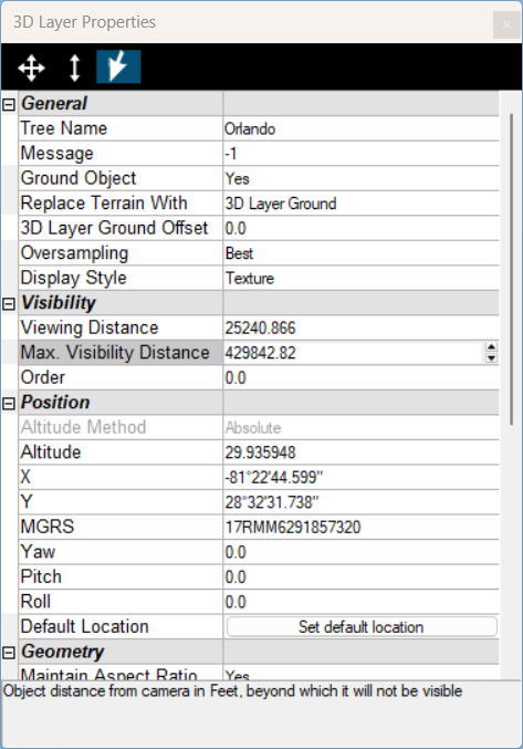
3D Layer Properties
|
Parameter |
Activity |
|
General |
|
|
Tree Name |
Type the description or name of the layer. This text appears in the Project Tree as the name of the layer. |
|
Activation Action |
Select the action to perform when selecting the layer from the Project Tree. |
|
Message |
The message associated with the layer. The number displayed is the number of the message. To create a new message, or update an existing message, open the Create Message dialog by clicking in this field and selecting Edit. See "Using the Create Message Dialog" in the "Working with Objects" chapter for more information. |
|
Ground Object |
Determines if the layer is calculated as part of the terrain’s elevation. |
|
Replace Terrain With |
Determines whether terrain imagery and elevation in the 3D layer area is replaced with the 3D layer's ground layer created by PhotoMesh or with the 3D layer's lower resolution data (Simplified Model), or not replaced at all. |
|
3D Layer Ground Offset |
Offset from the 3D layer ground for drawing and placement of "on terrain" and "relative to terrain" objects. |
|
Oversampling |
The 3D layer’s Level of Detail (LOD). When set to Normal, TerraExplorer determines the optimal quality to performance balance based on the current view. The "High" and "Best" settings will load higher quality blocks but are also more resource-intensive. |
|
Select a 3D layer display style. The model can include a wireframe and be textured, solid color, or semi-transparent (x-ray). § Texture § Texture + wireframe § Solid color § Solid color + wireframe § X-ray – Semi-transparent model, enabling you to see through all model walls Note: The Display Style can also be selected from the 3D Layer contextual tab. |
|
|
Visibility |
|
|
Default Viewing Distance |
Determines the viewing distance of the camera from the layer. This distance is used as a stop mark for any "Fly-to" or "View Object" operation. It is also used when selecting to edit the layer from the Project Tree. When this value is set to the default of -1, TerraExplorer calculates and sets the ideal viewing distance for the layer based on its size. |
|
Max. Visibility Distance |
Sets the maximal distance from the camera above which the layer disappears. |
|
Order |
Set the Draw Order of the 3D layer. Objects with higher Order values are drawn on top of objects with lower values. |
|
Position |
|
|
The altitude method used by the 3D layer. For 3DMLs, this property is read-only, always set to Absolute. Absolute places the 3D layer's pivot point at a specified altitude above the terrain database vertical datum base ellipsoid. |
|
|
Altitude |
The altitude, as defined in Altitude Method, for the 3D layer's pivot point. |
|
X |
The X-coordinate for the 3D layer's pivot point. |
|
Y |
The Y-coordinate for the 3D layer's pivot point. |
|
MGRS |
The coordinates for the 3D layer's pivot point in Military Grid Reference System (MGRS) coordinates. This field is only available if Show MGRS Coordinates was selected in the Options dialog. See "View" in the "Using TerraExplorer Options" chapter for more information. |
|
Yaw |
The direction angle of the 3D layer along the vertical axis relative to north. |
|
Pitch |
The tilt angle of the 3D layer along its lateral axis relative to the horizon. |
|
Roll |
The roll angle of the 3D layer along its longitudinal (front-to-back) axis. |
|
Default Location |
Repositions the 3D layer in its default location (according to the file’s geo-referencing information). |
|
Geometry |
|
|
Maintain Aspect Ratio |
Maintain the 3D layer's proportional relationship between the width, length, and height. If Yes is selected, when the scale factor in one axis is modified, the scale factor in the other two axes is automatically adjusted to maintain the original width:length:height ratio. If No is selected, the scale factor in each axis can be modified independently of the other axis scale factors. |
|
Scale X |
Determines the length on the X axis of the 3D layer. The actual X value of the 3D layer in the 3D World is the x value of the 3D layer in its internal coordinate system times the Scale X value. (i.e., if the 3D layer has an X value of 5 units and the Scale X is set to 10 meters per pixel, the X value of the 3D layer in the 3D World is 50 meters.) |
|
Scale Y |
Determines the length on the Y axis of the 3D layer. The actual Y value of the 3D layer in the 3D World is the Y value of the 3D layer in its internal coordinate system times the Scale Y value. (i.e., if the 3D layer has a Y value of 10 units and the Scale Y is set to 10 meters per pixel, the Y value of the 3D layer in the 3D World is 100 meters.) |
|
Scale Z |
Determines the height (Z value) of the 3D layer. The actual height of the 3D layer in the 3D World is the height of the 3D layer in its internal coordinate system times the Scale Z value. (i.e., if the 3D layer has a height of 5 units and the Scale Z is set to 10 meters per pixel, the height of the 3D layer in the 3D World is 50 meters.) |
|
Connection |
|
|
File Name |
Path to the 3D layer file. |
|
Mesh Layer Name |
Name of the 3D layer (Read-only). |
|
Projection |
|
|
Reproject Elevation |
Select the check box to reproject the layer’s elevation values to the terrain’s coordinate system. This option only applies when Altitude Method is set to Absolute. Geocentric layers are always reprojected. |
|
Layer Coord Sys |
The layer’s coordinate system (Read-only). |
|
Layer Bounding Box |
|
|
Upper Left X |
The X coordinate of the upper left corner of the layer (Read-only). |
|
Upper Left Y |
The Y coordinate of the upper left corner of the layer (Read-only). |
|
Upper Left MGRS |
The coordinates for the upper left corner of the layer in Military Grid Reference System (MGRS) coordinates. This field is only available if Show MGRS Coordinates was selected in the Options dialog. See "View" in the "Using TerraExplorer Options" chapter for more information (read-only). |
|
Lower Right X |
The X coordinate of the lower right corner of the layer (Read-only). |
|
Lower Right Y |
The Y coordinate of the lower right corner of the layer (Read-only). |
|
Lower Right MGRS |
The coordinates for the lower right corner of the layer in Military Grid Reference System (MGRS) coordinates. This field is only available if Show MGRS Coordinates was selected in the Options dialog. See "View" in the "Using TerraExplorer Options" chapter for more information (Read-only). |