Creating and Opening a PhotoMesh Project
When you create a new project, PhotoMesh creates an output folder with the same name as the project file for the project file and output files.
To start a new project:
1. From the File menu, select New (CTRL+N). The New Project dialog is displayed.
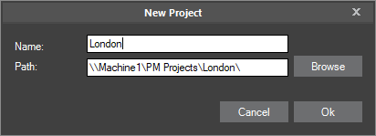
New Project on Local Drive / New Project on Network Drive
2. Browse to the required path for the project folder.
Note: PhotoMesh can take advantage of computer clusters to accelerate database creation. See the "Fusers" chapter for more information. To enable this, both the project folder and the working folder should be set to network folders with read-write access permissions, for both the master and client computers. It is recommended to use UNC format (\\[UNC Master] \folder\ProjectFolder, e.g.: \\Machine1\c\PhotoMesh\ProjectFolder and \\[UNC Master] \folder\WorkingFolder, e.g.: \\Machine1\c\PhotoMesh7.0\WorkingFolder), though a mapped network drive can also be used as long as the same letter is mapped to the same share on all computers. The shared project folder and working folder must both be on a device that supports the number of concurrent network connections you require, e.g., Windows 10 limits the number of supported concurrent connections to 20.
3. In the Name field, type a project name, and then click Ok. PhotoMesh creates an output folder (with the same name as the project file) for the project file and output files. The Add Photos Wizard is displayed. See the "Photo Management" chapter for more information.
Note: If PhotoMesh cannot load the default base terrain (generally because you are not connected currently to the Internet), the Terrain Database dialog is displayed. See "Setting the Terrain Database" in this chapter for more information.
To open an existing project:
1. From the File menu, select Open. The Open dialog is displayed.
2. Browse to the required file and click Open.
3. If PhotoMesh cannot load the default base terrain (generally because you are not connected currently to the Internet), the Terrain Database dialog is displayed. See "Setting the Terrain Database" in this chapter for more information.
Setting the Terrain Database
You can set the MPT or .FLY to use as the base terrain for your project.
To set the terrain database:
1. On the Home tab, in the Add group, click Terrain Database. The Terrain Database dialog is displayed.
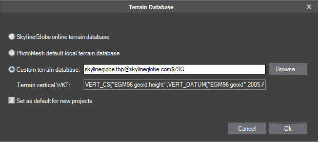
Terrain Database Dialog
2. Select one of the terrain database options:
§ SkylineGlobe online terrain database – To use the default terrain database ([email protected]).
§ PhotoMesh default local terrain database – To use the base terrain file included with the PhotoMesh installation (Default_Local_Terrain.mpt).
§ Custom terrain database – To use a custom terrain database. Browse to the required file.
3. If you want to set your selected option as the default for new projects, select the check box. The default terrain database for new projects is listed in the PhotoMesh Options dialog. See "Setting PhotoMesh Options" in the "Basic Concepts" chapter for more information.
4. Click OK.
Viewing Build Settings
The Build Settings dialog is used to view project parameters, such as AT and reconstruction settings, output coordinate system, and output formats. Build settings can only be edited when beginning a build or rebuild process. See "Setting Build Steps, Parameters, and Outputs" in the "Building" chapter for information.
To view Build Settings:
1. On the Home tab, in the Process group, click the arrow next to Build, and select View Build Settings. The Build Settings dialog is displayed, showing the simplified view that consolidates all the main settings under a single tab ("Build Settings"). See "Setting Build Steps, Parameters and Outputs" in the "Building" chapter for more information.
2. Click the tabs to view preset information and advanced AT and reconstruction parameters. See "Setting Build Parameters – Advanced Settings" in the "Building" chapter for more information.
Setting the Coordinate System
The Coordinate System Settings dialog is used to set and view the project’s internal coordinate system, in which aerotriangulation and reconstruction are performed. The coordinate system is also relevant for calculating the horizontal and vertical accuracy of the control points.
Note: When Review mode is on, you can only view the coordinate system.
To view Coordinate System Settings:
1. On the Home tab, in the Process group, click the arrow next to Build, and select Coordinate System Settings. The Coordinate System Settings dialog is displayed, showing the name of the project’s coordinate system.
Note: When Review mode is off, you can click the arrow to select a different coordinate system from the dropdown list. Select the Custom option to create a new custom coordinate system. See "Coordinate System" in the "Basic Concepts" chapter for more information.
2. Click View to view the full Well-Known Text (WKT) for the coordinate system.