Importing Control Points
Control point data can be imported in a tab delimited .gcp (text format) file:
§ First line (optional): Define the control points’ coordinate system in WKT format. (Default: geographic Lat-Long WGS84.)
wkt=……
Note: The WKT information must be in a single line without any line breaks. You can use the Coordinate System Generator to generate a WKT string defining the required coordinate system. See "Coordinate System" in the "Basic Concepts" chapter for more information.
§ Second line: sep=\t:
This sets the file as tab delimited.
§ Third line (optional): Select the template file for auto-marking of control points. The template file determines what marker type will be automatically identified in photos as a control point, e.g., checkboard or cross. See "Marking and Auto-Marking Control Points in Photos" in this chapter for more information. The template is saved in the AGCPTemplates folder under the application’s Fuser folder. Currently, the only template available is aeropoint.agcp.
template=aeropoint.agcp
§ Fourth line (optional): Indicate the number of control points. If this information is not provided, each subsequent line in the file is interpreted as providing positioning information for a distinct control point. If the file includes this information, all lines after the number of lines in cp=[number] are interpreted as mapping between control points and photos.
cp=[number]
§ For each control point, set the control point’s position on the terrain (X, Y, Altitude (Optional), Name (Optional), Type (Optional; Possible values: 1-control; 2-check; 3-tie) in tab delimited format.
[x coordinate] <TAB> [y coordinate] <TAB> [altitude] <TAB> [name] <TAB> [type]
Note: The Type parameter can only be passed together with the Name parameter.
§ Specify the position (in pixel coordinates) in a specified photo to associate with a particular control point (referenced by index) (optional).
[control point index] <TAB> [photo file path] <TAB> [x pixel coordinate] <TAB> [y pixel coordinate]
Example:
wkt=GEOGCS["WGS 84",DATUM["WGS_1984",SPHEROID["WGS 84",6378137,298.257223563,AUTHORITY["EPSG","7030"]],AUTHORITY["EPSG","6326"]],PRIMEM["Greenwich",0,AUTHORITY["EPSG","8901"]],UNIT["degree",0.0174532925199433,AUTHORITY["EPSG","9122"]],AUTHORITY["EPSG","4326"]]
sep=\t
cp=2
9.63390819201651 <TAB> 47.4233597051724 <TAB> 401.463806152344 <TAB> Control point1
9.63390818337074 <TAB> 47.4233597019402 <TAB> 401.463793239556 <TAB> Control point2
0 <TAB> C:\Photos\1.tif <TAB> 384 <TAB> 5456
0 <TAB> C:\Photos\2.tif <TAB> 7689 <TAB> 4761
0 <TAB> C:\Photos\3.tif <TAB> 8738 <TAB> 4340
1 <TAB> C:\Photos\4.tif <TAB> 388 <TAB> 5450
1 <TAB> C:\Photos\5.tif <TAB> 7690 <TAB> 4761
1 <TAB> C:\Photos\6.tif <TAB> 8741<TAB> 4326
To import control points:
1. On the Home tab, in the Add group, click the arrow under Control Points and select Import. The Import Control Point File dialog is displayed.
2. Browse to the required .gcp file and click Open. If the control point file only contains information about the control point’s position on the terrain but not about either the positions (in pixel coordinates) in photos to associate with each control point or the auto-marking template, then upon import of the file, the Auto-Mark Control Points dialog box is displayed asking if you want to auto-mark the photos. Select whether to use auto-marking and if Yes, what Marking template to use. See "Marking Control Points in Photos" step 9 in this chapter for more information.
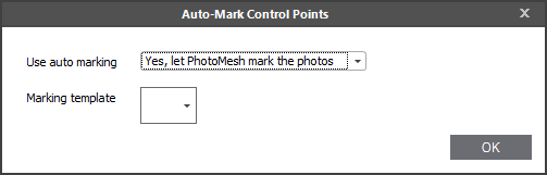
Auto-Mark Control Points Dialog
3. Modify the control point properties as required, and then save the project.