Marking and Auto-Marking Control Points in Photos
Control points are marked in photos using the Control Point Editor. Each control point should be marked in a few photos from each collection or photo direction. It is recommended to have at least 10 sampled photos for each control point.
In addition to the ribbon, the Control Point Editor includes a photo viewing window, a photos panel, and a sampled photos panel - that gradually becomes populated with photo thumbnails as you mark the control point in photos. The photos panel displays the photos from which to select the photos for marking control points, either as thumbnails or in table format with relevant photo information. You can also manually add photos to this list as described in the steps below.
Note: In order to enable your ground control points to be fully utilized in the AT process, it is recommended to add at least 3-5 ground control points per AT tile. When only two ground control points are provided, simple vertical adjustment, scaling and rotation are performed. When only one ground control point is provided, only vertical adjustment is performed. Any control point marked in fewer than three photos will be marked in red in the Control Point list.
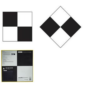
Auto-Marking Photos: If your photos include control point markers, PhotoMesh can automatically identify them and mark control points in photos based on them. You can select the template that corresponds to your marker type, e.g., checkboard or cross.After selecting a control point for auto-marking, this setting can be overridden by manually marking this control point in one or more photos. The automatic markers are added as regular markers to the photos only after aerotriangulation is performed.
Note: It is recommended to review the photos in Control Point Editor after performing aerotriangulation to see which were auto-marked with control points, so that you can add manual markers, if necessary.
Control Point Markers
To mark a control point in photos:
1. If the control point was not already created, create the control point. See "Creating Ground Control Points" and "Creating Tie Points" in this chapter for information. The Control Point Editor is displayed.
2. If the control point was previously created, in the Project Tree, select the Control and Tie Points group, and then in the Control and Tie Points list, right-click the required control point, and select Edit. The Control Point Editor is displayed.
Note: If the Control Point Editor is already open, selecting a control point in the Control and Tie Points list opens that point in the Editor.
3. The Control Point Editor by default is docked in the right-hand side of the PhotoMesh window. If you want to undock it, click Toggle Editor Docking ![]() . Click again to redock the Editor.
. Click again to redock the Editor.
4. From the Photos filter, select which photos should be listed or displayed in the Photos panel:
§ All in frustum (Calculated) – All the photos whose calculated frustum intersects the control point.
§ All in range (Calculated) – All photos with the selected control point in their calculated range (according to their Effective Range).
§ All in frustum (Original) – All the photos whose frustum intersects the control point.
Note: For photos with positioning and orientation information, this is determined based on frustum, and for photos with only positioning, according to the effective range set (See "Collection Property Sheet" in the "Photo Management" chapter for information).
§ All in range (Original) – All photos with the selected control point in their range (according to their Effective Range).
Note: This option is only available if photos have positioning information.
§ All in project (Original) – All photos in project (up to 2000 photos).
§ Custom selection (Best) – All photos selected in the Photos list before creating the tie point from the Photo tab. See "Creating Tie Points in Selected Photos" in this chapter for more information.
5. Select a viewing format for the Photos panel:
§ ![]() – View as thumbnails
– View as thumbnails
§ ![]() – View in table format with information about distance, sampling error, etc. for each photo
– View in table format with information about distance, sampling error, etc. for each photo
6. If viewing the photos in table format, select the column by which you want to sort the table (in ascending order). Select the column a second time to switch to descending order. For filtering and advanced sorting options, see "Filtering Data in the Control Point Editor" in this chapter for information.
7. To view a photo using the Photo Viewer, select the photo from either the Photos panel or Sampled Photos panel, and click View in Photo Viewer ![]() . See "Viewing Photos in the Photo Viewer" in the "Preparing the Project" chapter. The Photo Viewer opens in the Control Point window. Click Back to GCP Editor to close the Photo Viewer and redisplay the editor.
. See "Viewing Photos in the Photo Viewer" in the "Preparing the Project" chapter. The Photo Viewer opens in the Control Point window. Click Back to GCP Editor to close the Photo Viewer and redisplay the editor.
8. In the Photos panel, select the photo on which you want to mark the position of the selected control point. The photo is displayed in the photo viewing window with a white cross hairs indicating the projected location of the control point that PhotoMesh automatically calculated. Type ‘n’ to select the next photo, or ‘p’ to select the previous one.
Note: Any photo thumbnails that are outside of the current build area are displayed in strikethrough font.
9. To have PhotoMesh automatically identify control point markers in your photos and mark the photos in PhotoMesh accordingly, do the following:
a. Click ![]() Auto-Mark. The Auto-Mark Control Points dialog is displayed.
Auto-Mark. The Auto-Mark Control Points dialog is displayed.
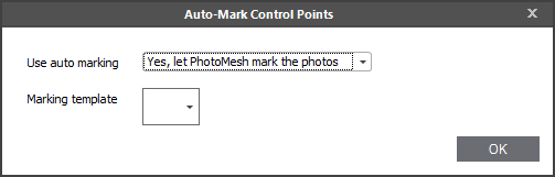
Auto-Mark Control Points Dialog
b. In the Use auto marking field, select Yes, let PhotoMesh mark the photos.
c. Select a Marking template. The template determines what marker type will be automatically identified by PhotoMesh as a control point, e.g., checkboard or cross. A dialog box is displayed asking whether you want to perform auto-marking of photos using the selected template for all the control points.
d. Click Yes if you want to auto-mark all the control points in all the photos. After selecting a control point for auto-marking, this setting can be overridden by manually marking this control point in one or more photos. If any of the photos a control point is found in were set for auto-marking, the Auto-GCP check box is selected for this control point in the Control and Tie Points list. The automatic markers are added as regular markers to the photos only after aerotriangulation is performed.
Note: It is recommended to review the photos in the Control Point Editor after performing aerotriangulation to see which were auto-marked with control points, so that you can add manual markers, if necessary.
10. If manually marking control points, find the correct position in the photo in which to mark the control point. Use the mouse to zoom in and out and pan in the photo or use the ribbon commands:
|
|
Zooms in. |
|
|
Zooms out |
|
|
Zoom in to the marked control point. This command is only available after a control point was marked in the photo. |
11. Click ![]() Sample in Photo, and then click on the photo where you want to set the position of the control point. You can also type ‘s’ on the keyboard to toggle between navigation and sampling modes. A red crosshairs is displayed where you clicked in the 3D Window and in the corresponding position on the photo thumbnail which is added to the "Sampled Photos" panel. The photo’s XY pixel coordinates are displayed in the Mark X and Mark Y fields on the Control Point Editor ribbon in the Control Point group. If the Photos panel is displayed in table format, the check box in the Marked column is selected (If displayed as thumbnails, a check is displayed on top of the reviewed photo). The following information is displayed in the photo viewing window:
Sample in Photo, and then click on the photo where you want to set the position of the control point. You can also type ‘s’ on the keyboard to toggle between navigation and sampling modes. A red crosshairs is displayed where you clicked in the 3D Window and in the corresponding position on the photo thumbnail which is added to the "Sampled Photos" panel. The photo’s XY pixel coordinates are displayed in the Mark X and Mark Y fields on the Control Point Editor ribbon in the Control Point group. If the Photos panel is displayed in table format, the check box in the Marked column is selected (If displayed as thumbnails, a check is displayed on top of the reviewed photo). The following information is displayed in the photo viewing window:
|
|
User sample for position of control point. |
|
|
Projected location of control point. |
|
|
Projected triangulation – Projection of the triangulation center (adaptive weighted median of all ray intersections) back to the photos. |
|
|
Sampling error - RMS |
|
Sampling Error - Photo |
Distance, in pixels, between the projected triangulation and the user sample in this photo. |
|
Sampling Errors - RMS |
Root mean square (RMS) of all distances, in pixels, between the projected triangulation and the user sample in all photos. |
|
Horizontal Error |
Horizontal distance, in meters, between the projected triangulation and the control point position. |
|
Vertical Error |
Vertical distance, in meters, between the projected triangulation and the control point position. |
12. If you want to modify the photo’s XY pixel coordinates, in the Control Point Editor, in the Mark X and Mark Y fields, type the required values.
13. If you want to clear the previously marked position of a control point, in the Control Point Editor, click ![]() Clear from Photo. The photo is removed from the "Sampled Photos" panel and the check is cleared from that photo thumbnail in the Photos panel.
Clear from Photo. The photo is removed from the "Sampled Photos" panel and the check is cleared from that photo thumbnail in the Photos panel.
Note: Only one position can be marked in each photo. If an additional position is marked, the previously marked position is automatically deleted and replaced by the new position.
14. Repeat steps 6-11 for each of the photos in which you want to mark the selected control point.
Filtering Data in the Control Point Editor
To filter control point lists in the Control Point Editor:
1. Point to the column by which you want to filter, and click the Filter icon ![]() . See "Filtering Data" and "Filter Editor" in the "Using the Project Tree and Item List" chapter for information.
. See "Filtering Data" and "Filter Editor" in the "Using the Project Tree and Item List" chapter for information.
2. Click Close. The applied filter(s) are listed at the bottom of the Photos panel, e.g., ![]() . Click X to remove a filter.
. Click X to remove a filter.
3. To access additional sorting commands, right-click any column header. Select any of the following commands:
|
Command |
Description |
|
Sort Ascending |
Sort all data in the table by this column in ascending order. |
|
Sort Descending |
Sort all data in the table by this column in ascending order. |
|
Clear All Sorting |
If multiple columns were sorted, this option is displayed to clear all. |
|
Group by This Column |
Group the data by this column. Note: If you want to clear the grouping, right click above the column headers, and select Clear Grouping. |
|
Show Group by Box |
Display boxes, above the photo table, indicating how the data is grouped in the table. Note: If you want to clear the Group by boxes, right click above the column headers, and select Hide Group by Box. |
|
Hide This Column |
Hide the selected column |
|
Column Chooser |
Customize which columns show in the table. Drag and drop columns to and from the Customization dialog. |
|
Best Fit |
Adjust the selected column’s width for the best fit for its contents. |
|
Best Fit (all columns) |
Adjust the all the table’s column widths for the overall best fit. |
|
Filter Editor |
Open the Filter Editor to edit the table filter. You can use the Filter Editor to add and remove conditions. A search expression can consist of more the one condition. In this case, you need to insert a connector between the conditions to specify their relations. In addition to AND, you can use the OR, NOT and [] connectors to define the relations between conditions. |
|
Show Find Panel |
Show a Find panel to search for a specific text. Note: To hide the Find panel, click the X next to it. it. |
|
Show Auto Filter Row |
Display a row with a filter option for each of the columns. |
Control Point Editor Keyboard Shortcuts
The following keyboard shortcuts are available:
|
Shortcut |
Description |
|
s |
Toggle between navigation and sampling modes. |
|
n |
Selects the next photo in the Photos panel and displays it in the photo viewing window. |
|
p |
Selects the previous photo in the Photos panel and displays it in the photo viewing window. |
|
N |
Selects the next control point in the Control Points table. |
|
P |
Selects the previous control point in the Control Points table. |