Loading LiDAR Data
LiDAR data can be loaded into a PhotoMesh project and integrated with project photos to supplement project data and increase model accuracy. PhotoMesh supports LiDAR data in .las, .laz or .e57 formats. To improve the reconstruction of the model, LiDAR data can be loaded together with a trajectory file that provides information about the scanner’s position while capturing the point cloud. Some .e57 files include internal trajectory information and therefore do not require an external one. LiDAR are converted to CPT, PhotoMesh's internal format, during the build's data preparation step or by Showing Point Cloud. See "About Building" in the "Building" chapter and "Showing a LiDAR Point Cloud on the Terrain" in this chapter for more information.
If LiDAR files are loaded after aerotriangulation is performed and reconstruction has already started, all reconstruction tiles that intersect with the new LiDAR’s bounding box are restored to the point cloud step. This ensures that all necessary processing is performed when the Build Start From step is set to Auto. See "Setting Build Steps" in the "Building" chapter for more information.
To load LiDAR files from your local disk:
1. On the Home tab, in the Add group, click the arrow next to LiDAR, and select one of the following:
§ Load files – To add selected files.
§ Load folder – To add an entire folder. All supported LiDAR files in the folder are loaded.
2. Browse to the required folder/file(s) and click Open.
3. Set the LiDAR’s coordinate system including its vertical datum.
Note: If incorrect coordinate system information is entered, the *.CPT created for the LiDAR should be manually deleted from the project's cpts directory: .\[PROJECT_NAME]\cpts\
4. Add a trajectory file and modify LiDAR properties, as required, in the LiDARs list. See "Modifying LiDAR Properties" and "Associating a LiDAR Point Cloud with its Trajectory Data" in this chapter for information.
Modifying LiDAR Properties
LiDAR data can be viewed and modified in the LiDARs list and point cloud properties dialog. This dialog is accessed from a right-click menu as described below.
To display and modify LiDAR point cloud properties:
1. In the Project Panel select the LiDARs group, and then in the LiDARs list, select the required LiDAR.
2. For basic properties such as path and coordinate system, in the LiDARs list, select the check boxes of the required LiDARs, and modify their properties as required. See "LiDARs List" in this chapter for more information.
Note: You can also search the list for the required LiDAR. See "Selecting Items Using the Item List" in the "Basic Concepts" chapter for information.
3. For point styling properties and other properties relating to how the point cloud is displayed, right-click the required LiDAR, and select Style Point Cloud. The Point Cloud Properties dialog is displayed. See "LiDAR Point Cloud Properties Dialog" in this chapter for more information.
Note: A LiDAR must be converted to CPT, PhotoMesh's internal format before it can be styled. You can convert the LiDAR by performing the build's data preparation step or by Showing Point Cloud. See "About Building" in the "Building" chapter and "Showing a LiDAR Point Cloud on the Terrain" in this chapter for more information.
LiDAR Point Cloud Properties Dialog
|
Property |
Description |
|
|
Style |
||
|
Point Size |
Size, in pixels, of each of the LiDAR point cloud’s points. If you want to base the point size on attribute fields, click the Field by Attribute button |
|
|
Point Color |
Color of the LiDAR point cloud points. This can be set to either of the following: § A set color value for all the points. To select a color, click Edit and select a color. § Based on a specific attribute field - To base each point of the point cloud’s color on a specific attribute field’s value, click the Field by Attribute button |
|
|
Point Visibility |
Determines if the LiDAR point cloud’s points are visible. To set the visibility of points based on their attribute values, click the Field by Attribute button |
|
|
Intensity Blend |
Determines how much the LiDAR point cloud’s intensity value is factored in colorizing the point cloud, where 0% colorizes the point cloud model by point color only, and 100% colorizes by intensity only. |
|
|
Oversampling |
The LiDAR point cloud’s Level of Detail (LOD). When set to Normal, PhotoMesh determines the optimal quality to performance balance based on the current view. The "High" and "Best" settings will load more points but are also more resource-intensive. |
|
|
Flatten Underlying Terrain |
Determines if the terrain under the model is leveled to the model’s elevation value. This option is enabled only if the Altitude Method property in the point cloud property sheet is set to Absolute. |
|
|
Hide Underlying Terrain |
Hides the terrain texture under the LiDAR point cloud model (the terrain appears as a black image). |
|
LiDARs List
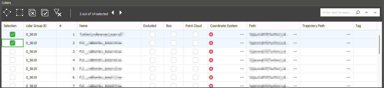
In the LiDARs list, you can view and set the LiDAR’s coordinate system, path and trajectory path, as well as set LiDAR visibility and inclusion in the project. See "About the Item List" in the "Basic Concepts" chapter for information on working with the LiDARs list.
LiDARs List
To open the LiDARs list:
§ In the Project Panel, select the LiDARs group. The LiDARs list includes all the LiDAR files in the project, and the following information:
|
Property |
Description |
|
Selection |
Select the check box to select the LiDAR in the 3D Window. |
|
LiDAR Group ID |
ID of the LiDAR group. |
|
# |
Number of the LiDAR. |
|
Name |
Name of LiDAR file. |
|
Excluded |
Select the check box to exclude the LiDAR point cloud from the project. |
|
Box |
Select the check box to show the LiDAR's bounding box. |
|
Point Cloud |
Select the check box to show a LiDAR point cloud on the terrain. |
|
Coordinate System |
Coordinate system of the LiDAR point cloud. Click Select |
|
Path |
Full path to the LiDAR point cloud. |
|
Trajectory Path |
Full path to file that provides information about the scanner’s position while capturing the point cloud. See "Associating a LiDAR Point Cloud with its Trajectory Data" in this chapter for more information on trajectory files. |
|
LAS Sample Point Time |
If the LAS/LAZ file included timestamps, this is a sample timestamp from the file in standard date and time format, based on the file’s Time Reference. |
|
Trajectory Min Time |
Minimum time in the trajectory dataset, i.e., the first timestamp in the trajectory file that successfully aligns with the LiDAR points. |
|
Trajectory Max Time |
Maximum time in the trajectory dataset, i.e., the last timestamp in the trajectory file that successfully aligns with the LiDAR points. |
|
Tag |
Free text about the LiDAR |
Associating a LiDAR Point Cloud with its Trajectory Data
Trajectory data provides details about the scanner's position during the capture of the LiDAR point cloud. This data can be loaded directly from a tab-delimited .trjt (text format) file or from a CSV/TXT file, which PhotoMesh will automatically convert to .trjt for processing.
Note: Some .e57 files include internal trajectory information and therefore do not require an external one.
Trajectory File Format
Trajectory data can be added in a tab delimited .trjt (text format) file that includes the following lines:
§ First line: Define the LiDAR version (Should always be 1.0)
#version=1.0
§ Second line: Define the LiDAR’s coordinate system in WKT format.
#wkt=……
Note: The WKT information must be in a single line without any line breaks. You can use the Coordinate System Generator to generate a WKT string defining the required coordinate system. See "Coordinate System" in the "Basic Concepts" chapter for more information.
§ Third line (optional): Indicates a time offset that should be added to the GPS time field in each record. This is equivalent to the trajectory file’s time base converted to seconds (default is 0 for the Unix Epoch 01/01/1970 timebase).
#timebase=
§ For each known scanner position, add a separate line with the scanner’s position (X, Y, Altitude) and the time the position was recorded (GPS Time) in tab delimited format. The scanner positions should be ordered chronologically.
[x coordinate] <TAB> [y coordinate] <TAB> [altitude] <TAB> [GPS time]
Note: The GPS Time is the double floating point time tag value at which the scanner’s position was recorded. This data must be in the same units and offset as the time data in the LiDAR file.
Example:
#version=1.0
#wkt=GEOGCS["WGS 84",DATUM["WGS_1984",SPHEROID["WGS 84",6378137,298.257223563,AUTHORITY["EPSG","7030"]],AUTHORITY["EPSG","6326"]],PRIMEM["Greenwich",0,AUTHORITY["EPSG","8901"]],UNIT["degree",0.0174532925199433,AUTHORITY["EPSG","9122"]],AUTHORITY["EPSG","4326"]]
#timebase=0
9.63390819201651 <TAB> 47.4233597051724 <TAB> 401.463806152344 <TAB> 583.161876711994
9.63390818337074 <TAB> 47.4233597019402 <TAB> 401.463793239556 <TAB> 583.161876711994
9.63390817652904 <TAB> 47.4233597069347 <TAB> 401.463349871528 <TAB> 583.161876711994
9.63390818337074 <TAB> 47.4233597019402 <TAB> 401.463407984571 <TAB> 583.160397257656
Associating a LiDAR File with Trajectory Data
To associate a LiDAR file with its trajectory data:
1. In the Project Panel select the LiDARs group, and then in the LiDARs list, select the required LiDAR and double-click the three dots ![]() in the Trajectory Path column. The Load a Trajectory File dialog is displayed.
in the Trajectory Path column. The Load a Trajectory File dialog is displayed.
2. If your trajectory file is in tab-delimited .trjt format, browse to the file, and click Open. The trajectory file is loaded into the project.
3. If your trajectory information is saved in a .txt or .csv file, the Load Trajectory from List dialog is displayed so you can enter trajectory settings and map the csv/txt file’s information to trajectory properties.
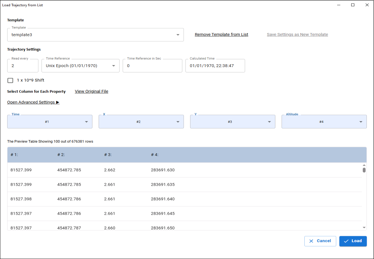
4. If you previously saved a template for mapping the csv/txt file’s information to trajectory properties, select this template. To save a new mapping of columns and properties as a template, click Save Settings as New Template. Then in the dialog that is displayed, enter a name for the template, and click Save.
5. Enter the trajectory settings:
§ Read Every - The interval at which the trajectory data is read, e.g., a value of 2 means the system will process trajectory data at a 2-second interval.
§ Time Reference - The starting point for time calculations, e.g., GPS Epoch starts on June 1, 1980. All timestamps in the trajectory file are calculated relative to this reference.
§ Time Reference in Seconds - Time Reference converted to seconds.
§ Calculated Time – Displays the first timestamp in the trajectory file in standard date and time format, based on the selected Time Reference.
6. Click Open Advanced Settings to specify the location of headers and data within the trajectory file and choose the delimiter (e.g., comma, tab) used for parsing the file data If there are no headers in your file, select the No Headers checkbox.
7. Map each property name (Time, X, Y, Altitude) to the correct column number in the trajectory file. If a template was applied, this may not be necessary. Use View Original File or the Preview Table to help verify mappings.
8. Click Load to load the trajectory information into PhotoMesh. Edit the LiDAR properties as required. See “Modifying LiDAR Properties” in this chapter for information.