Exporting 3D Mesh Layers to Models, Point Cloud, and ATAK
Mesh layers or sections of layers, e.g., subset areas or buildings, can be exported to any of the following data types: individual 3D models, LAS point cloud layers, or ATAK (for use with the ATAK mobile application). Export is supported for all mesh layers except for imported 3D Tiles and BIM, 3DML created from models feature layers, and 3DML from SGS that do not have edit permission.
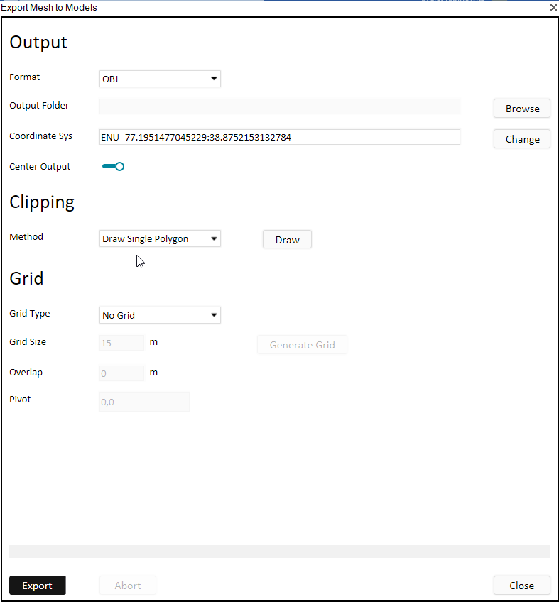
The areas for export can be defined in any of the following ways:
§ By selecting a feature layer
§ Using polygons from the clipboard
§ Drawing a polygon
The number of files created for each polygon depends on the grid size setting that you select. You have the option to split the extracted area into either 3D boxes or a 2D grid.
In addition to the export methods supported from TerraExplorer user interface, additional export options can be performed from the SLMeshConverter command line tool. See "Importing and Exporting Using the Command Line" in this chapter for information.
To export a mesh layer to individual models/ LAS point cloud / ATAK:
1. Select the mesh layer, and then on the 3D Mesh Layer tab, in the Mesh Layer group, click the arrow next to Export to Models and select the required option. The Export dialog is displayed.
2. Set the properties as required:
|
Format |
Select the output format. The options available depend on the export option selected: § Export to Models - OBJ, DAE, GLB, FBX § Export to Point Cloud – LAS, LAZ § Export to ATAK – ATAK OBJ |
|
Sample Resolution |
Set the sample resolution in meters. This field is only displayed for LAS/LAZ point cloud output. |
|
Output Folder |
Browse to the folder where you want to save the outputted files. |
|
Coordinate System |
The coordinate system is automatically set to the mesh's coordinate system. If you want to change it, click Change and set the required coordinate system. See “Coordinate System Dialog” in the “Basic Concepts” chapter for information. |
|
Center Output |
Re-center the coordinate system so that the origin (or reference point) is at the bottom-left corner of the mesh. This ensures that the coordinates are much smaller numbers, relative to the large original coordinates, making them easier to manage. |
|
Clipping Method |
Select your method of clipping the mesh area that you want to export: § Entire Mesh - Export the entire 3D mesh layer. § Draw Single Polygon – Mark a specific mesh section for export by drawing a polygon around it. Then click Draw to draw the polygon. § Feature Layer - Export the areas, e.g., buildings or subset areas, defined by a feature layer. Then drag and drop a feature layer from the Project Tree into the dialog. § Polygons from the Clipboard – Select the areas for export based on the clipboard polygons. Then click Copy from Clipboard. |
|
Grid Type |
Select the Grid Type: No grid, 2D, or 3D boxes. This determines how the selected mesh section is partitioned. § No Grid – No grid is used to divide the mesh area. Instead, a single file is produced for each clipping polygon, unless the clipping polygon is very large. The maximum texture size per file is approximately 1024 x 1024 pixels. § 2D Grid – The mesh area is divided only along x and y axes into uniform squares. Each square captures all data from the base to the top in that particular grid area, extending from the lowest to the highest points. § 3D Boxes – The mesh area is divided along the x, y and z axes, axes, allowing for complex three-dimensional data such as tall buildings or utility poles to be split into multiple files. |
|
Grid Size |
Set the size in meters for each square or box. A smaller grid size will result in smaller exported models. If the grid size is too large, multiple files will be created for a single square or box. |
|
Grid Overlap |
Specify the amount of overlap, in meters, between adjacent squares or boxes. |
|
Pivot |
Set the coordinates of the grid pivot. |
3. Click Generate Grid to generate the grid.
4. Click Export.