Comparison tools
The following comparison tools are available:
Swipe 3D, point cloud, and imagery layers
The Swipe Layers tool helps you detect the changes between two layers in the same location of any of the following types: 3D, point cloud, or imagery, or between one of these layer types and the base terrain. Using the tool, you can horizontally swipe between them, dynamically revealing and hiding parts of each layer.
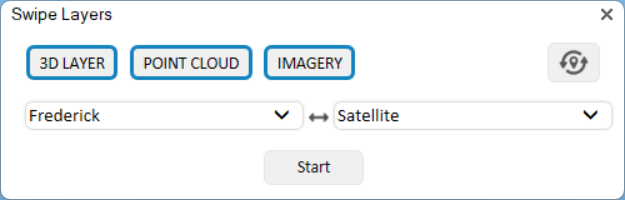
Swipe Layers Tool
To use the Swipe Layers tool:
1. Zoom in on an area with two visible layers, or with a single layer that you want to compare to the base terrain.
2. On the Analysis tab, in the Comparison group, click the arrow under Swipe, and select Swipe Layers. The Swipe Layers controls are displayed.
3. Click any of the following: 3D, Point Cloud, and Imagery to filter the selection to the layer type(s) you want. If you want to refresh the dropdown layers and automatically detect and select the layers in current view, click Refresh & Auto-Select  .
.
4. Select the layers from the two dropdown lists, and click Start.
Note: If the Swipe Layers tool is unable to detect the model, zoom out to view the base of the model.
5. If comparing 3D layers, select the display style:
§ Texture
§ Texture + wireframe
§ Solid
§ Solid + wireframe
§ X-ray - Semi-transparent model, enabling you to see through all model walls
6. Slide the slider all the way to the right to completely show the first layer, and all the way to the left to completely show the second one. As the slider moves between these extremes, the first layer is gradually clipped to reveal the second one.
7. Click Auto-Repeat  to automatically loop the slider value between 0-100% to dynamically change the top layer clipping. Click Freeze at any point to freeze the slider at a specific value.
Swipe snapshots
The Swipe Snapshots tool helps you create and compare snapshots showing different versions of the area in view in the 3D Window by showing or hiding objects in the Project Tree.

Swipe Snapshots Tool
To use the Swipe Snapshots tool:
1. In the 3D Window, navigate to the required area, and then create the required scene by using the Project Tree to show or hide objects.
2. On the Analysis tab, in the Comparison group, click the arrow under Swipe, and select Swipe Snapshots. The Swipe Snapshots dialog is displayed.
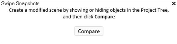
Create Modified Scene
3. Create a modified scene by showing or hiding objects in the Project Tree, and then click Compare.
4. When the snapshot is generated, use the following controls:
§ Mode selection – Defines how the modified scene is revealed relative to the original scene:
§ Right–Left – A vertical divider moves horizontally, revealing the modified scene from right to left.
§ Top–Bottom – A horizontal divider moves vertically, revealing the modified scene from top to bottom.
§ Transparency – The modified scene is overlaid on the original, and its opacity is adjusted.
§ Slider control – Adjusts the comparison level:
§ In Right–Left and Top–Bottom modes, the slider moves the dividing line across the scene, controlling how much of each scene is visible.
§ In Transparency mode, the slider controls the opacity of the modified scene. Moving the slider increases or decreases its transparency, allowing you to see more or less of the original scene beneath it.
Elevation difference
The Elevation Difference tool analyzes the elevation difference between two layers of any of the following types: elevation, feature, point cloud or 3D, or between a layer and base terrain in a defined polygonal area. It provides a clear, spatial representation of elevation change while filtering out differences that you define as insignificant. This allows you to carefully compare before and after states, e.g., the state of an area before and after a landslide or volcano, or before and after mining restorative efforts.
The analysis area is defined either by a drawn polygon or by objects already on the clipboard. The output of the analysis is a text label with the analysis results and two point cloud layers, each representing a different direction of elevation change within the analyzed area.
§ Yellow point cloud – Points where Layer 1 is higher than Layer 2
§ Cyan (blue-green) point cloud – Points where Layer 2 is higher than Layer 1
Each point corresponds to a sampled location where the elevation difference exceeds the specified Min Difference value. Hover over any point on either point cloud to display a tooltip with the elevation and volume difference at that point.
A summary is also generated, with statistics on the percentage of points in which each layer was higher and the maximum elevation difference between the two.
Note: The visibility of layers or objects in the designated area that are not part of the comparison should be turned off, so that the comparison results are not affected.
To use the Elevation Comparison tool:
1. On the Analysis tab, in the Comparison group, click Elevation. The Elevation Difference dialog is displayed.

Elevation Difference
2. Click any of the following: 3D Layer, Point Cloud, Elevation or Feature to filter the selection to the layer type(s) you want. If you want to refresh the dropdown layers, and automatically detect and select the layers in current view, click Refresh & Detect. Only layers that are calculated as part of the terrain’s elevation (i.e., their "Ground Object" property is set to yes) are included in the dropdown lists.
3. Select two layers for comparison, or a layer and base terrain.
4. Select the Quality of the result layer. This determines the accuracy level by which the analysis is performed. Select one of the following options:
§ Low – Performs approximately 16K samples
§ Medium – Performs approximately 65K samples
§ High – Performs approximately 260K samples
5. In the Min Difference field, select the minimum elevation difference between the layers that should be marked.
6. Select either of the following methods to mark your area of interest:
§ Draw Area – The area is marked by drawing a polygon in the 3D Window. If this option is selected, left-click in the 3D Window to place the polygon waypoints, and right-click to complete.
§ From Clipboard – Analysis is performed in the locations of all polygon clipboard objects. The polygons must be on the clipboard before selecting this option.
7. After the analysis is complete, a results dialog is displayed. These results are saved in the Project Tree as a text label.
§ Percentage of sampled points for which the elevation difference between the layers was greater than the Min Difference set.
§ Percentage of sampled points above Min Difference in which Layer 1 was higher than Layer 2.
§ Percentage of sampled points above Min Difference in which Layer 2 was higher than Layer 1.
§ Maximum elevation difference in which Layer 1 was higher than Layer 2.
§ Maximum elevation difference in which Layer 2 was higher than Layer 1.
8. Review the elevation difference results, graphically represented by the generated point cloud layers. Only elevation differences. that are above the Min Difference that you set, are marked:
§ Yellow – Layer 1 is higher than Layer 2
§ Cyan (Blue-green) – Layer 2 is higher than Layer 1
Point to any point on the point clouds to display a tooltip with the elevation and volume difference at that point.
9. The elevation difference results are automatically exported to point cloud layers listed in the Project Tree and saved under the application AppData. You can find the full path to these point clouds in the layers' property sheets, in the File Name property.