Photo inspector tool
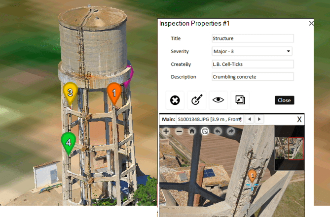
The Photo Inspector tool displays the photos used to generate a PhotoMesh 3D model so you can view and inspect any section of your model (tower, bridge, construction site, etc.) together with the source photos used to produce it. Photo Inspector makes it easy to navigate within the model and between the model and its associated photos, so you can find the best photos for each area of the model.
The Photo Inspector also provides a set of drawing and measurement tools to mark areas and locations on the model and generate a detailed report with all inspection details.
Starting the Photo Inspector tool
To perform photo inspections, the Photo Inspector tool requires access to the PhotoMesh 3D model output (3DML) and the photos layer generated by PhotoMesh's aerotriangulation process. The tool also needs access to the folder or server containing the original photos used by PhotoMesh.
To start the Photo Inspector tool:
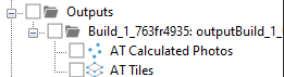
1. Load the output FLY file produced in a PhotoMesh project (outputs.fly) into your TerraExplorer project. To determine the location of this file, in PhotoMesh, open the project with your generated output. Then in the Build Outputs list, select Open Project Folder, or Open in TerraExplorer to open the output in TerraExplorer directly from PhotoMesh. See PhotoMesh User Guide for more information. When this file is loaded into the project, an Outputs group is created in the Project Tree that contains two shapefiles: AT Calculated Photos and AT Tiles. E.g.,
Note: It is recommended to save a copy of the PhotoMesh outputs.fly project to another location or publish it to SkylineGlobe Server. You can publish PhotoMesh projects with photos to SkylineGlobe Server from the Publish Project with Photos to SGS setting.
2. On the Tools tab, in the PhotoMesh group, click Photo Inspector. The Photo Inspector dialog is displayed.
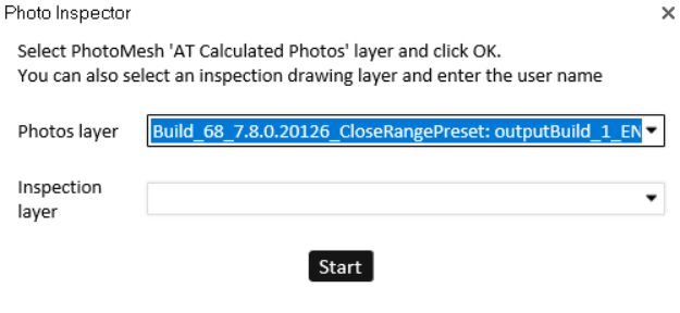
Photo Inspector
3. The Photos layer field is automatically populated with the AT Calculated Photos layer in the project. If there are multiple Calculated Photos layers, select the required layer from the dropdown list.
4. The Inspection layer dropdown is automatically populated with all polyline and polygon feature layers in the project. See "Using Inspection Layers" in this chapter for more information.
5. Click Start. The Photo Inspector Quick Guide is displayed.
Setting an inspection point (point of interest)
To set an inspection point:
1. In the Photo Inspector Quick Guide, click Zoom in  to view the inspection area.
2. Click Set inspection point  (Shortcut key: "m") and then click on the model in the point of interest. The photos looking at the point are listed in the Photo Inspector lists under the main and secondary viewers. In the 3D Window, photo icons are displayed for each of the photos looking at the point.
3. If the photo viewers are displayed, you can select a new point of interest by clicking Set inspection point , and then clicking on one of the photos.
4. Use the Reset  button on the toolbar to clear the inspection point, close the photo viewers and reset the visibility filter on the photo’s layer in the 3D Window to view all photo icons.
Photo inspector lists
To be listed in the viewers' Photo Inspector lists, a photo must meet the following conditions:
§ Its location is within the Settings-Search distance value of the point of interest.
§ It was calculated by PhotoMesh's aerotriangulation process.
§ The point of interest was projected within the photo frame but not too close (> 50 pixels) to the edge of the photo.
The number of photos listed in the viewers is determined by the Max Results per Viewer setting. The photos are listed in order from most relevant to the point of interest to least relevant according to the following criteria:
§ Distance between the photo and the selected point
§ Angle of the camera to the selected point in comparison to the viewer angle
If the selected point is on a horizontal surface (road, roof), more weight is given to the distance factor. If the selected point is on a vertical surface, more weight is given to the angle.
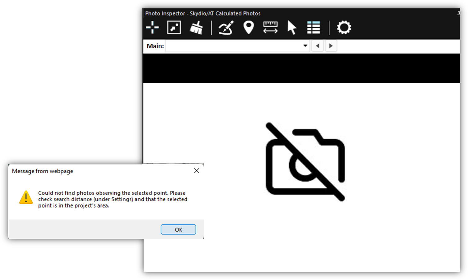
If there are no photos that meet the filter criteria, the photo viewer displays a "no photo" image and a message that no photos were found.
Using the photo viewers (main and secondary)
After selecting a point of interest, the Photo Inspector selects the most relevant photo and zooms in to the selected point on the photo in the photo viewer. The selected point is marked by a blue crosshairs  on the photo and on the 3D model. All the photos looking at the point that meet the criteria listed above, are listed in the Photo Inspector under the main and secondary viewers:
The Photo Inspector includes two viewers as described below. In Settings, you can set whether to show only a single viewer (main) or whether to show also a secondary viewer:
§ Main photo viewer – If only one viewer is set, then the main viewer shows all photos. If two viewers are set, then the main viewer shows either only RGB photos or only photos looking at the point of interest from the front and above (depends on the secondary photo viewer settings).
§ Secondary photo viewer – The secondary photo viewer is used to display alternative photos to the main viewer. There are two options for the secondary viewer:
§ From Alternative Direction: Photos looking at the point of interest from the left, right, and behind.
§ Non-RGB Photos: If the project contains RGB and non-RGB collections, the secondary viewer can be used to view the non-RGB photos (e.g., NIR, thermal). In this case, the main viewer displays RGB photos from all angles and the secondary viewer displays non-RGB photos from all directions.
Switching between single and multiple viewers
To switch between single and multiple viewers:
§ On the Photo Inspector toolbar, click 
 to toggle between a single viewer (main) and two viewers (main and secondary). You can also toggle on/off this option from the Settings dialog (Show secondary viewer )
Selecting the photos to be displayed
To set the photos to be displayed in the secondary viewer:
§ In Settings, select either of the following:
§ From alternative direction - Photos looking at the point of interest from the left, right, and behind
§ Non-RGB collections - e.g., NIR, thermal
Attaching the secondary viewer to the main viewer
Attaching the secondary viewer to the main one links the two viewers so that the secondary viewer moves to focus on the same center point as in the main viewer, whenever you drag or zoom in the main viewer. If the center point doesn't exist in the photo shown in the secondary viewer, a black photo is displayed.
To attach the secondary photo viewer to the main viewer:
§ In Settings, toggle on the Attached to Main option.
Viewing the inspection point in the photos
After selecting a point of interest, the Photo Viewer’s Photo Inspector lists show the most relevant photos according to the Max Results per Viewer setting.
To view the inspection point in the photos, do any of the following:
§ Select a photo in the viewers' dropdown photo lists.
§ Use the Next/Previous buttons  or the keyboard shortcuts "<", ">" to browse through the photos.
§ In the 3D Window, click any camera icon to display the photo associated with it in the relevant viewer (main or secondary).
§ Use the Photo Inspector's on-screen controls to inspect a photo in the viewer. If you don’t see the on-screen controls, hover with the mouse at the top of the viewer:
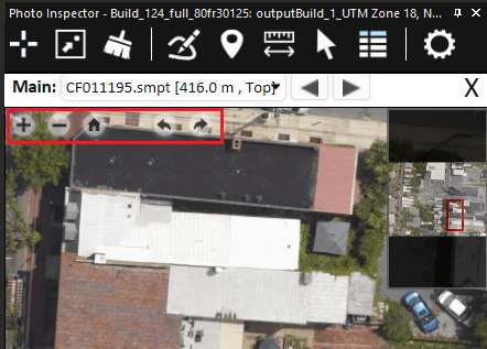
§  and
and  to zoom in and out
§  and
and  to rotate left and right
§  zoom out to see entire photo
§ Hover over a photo in the main or secondary viewer to display a virtual cursor  on the 3D model in the 3D Window in the same location. This virtual cursor indicates the location of the hovered position on the photo.
Publishing a project with photos to SGS
When publishing the TerraExplorer project to SGS, all photos associated with the AT inspection layer can also be published.
Note: This capability is only available for SGS 7.3.1 or higher.
To publish:
§ Click Publish to publish the photos linked to this layer when publishing to SGS. Then in the Publish to SGS dialog that is displayed, click Publish.
When opening the published project, the online photos layer has a new attribute field called "das_userfilename" that contains the online address of each photo. Photo Inspector automatically identifies this attribute value and works with the online resources.
Using inspection layers
Use the Photo Inspector tool to mark up and measure areas on your 3D model or on photos. You can then save this information in a new layer specifically created for this purpose, or in any existing polyline or polygon feature layer that has been loaded into the project as an inspection layer.
The model or photo can be marked with inspection points, polylines, or polygons. An HTML or PDF inspection report can then be generated with information about the project and all inspection markings and measurements.
Creating and selecting inspection layers
Either select an inspection layer already loaded to your TerraExplorer project or create a new layer.
To select an inspection layer, do either of the following:
§ Select the inspection layer from the initial Photo Inspector dialog.
§ In Settings, the Inspection layer field is automatically populated with all polyline and polygon feature layers in the project, whether created in the project or loaded into it. Select the required layer from the list.
To create a new inspection layer:
1. In the Photo Inspector Settings, Create inspection layer field, click Create. The New Inspection Layer dialog is displayed.
2. Type a name for the layer and define custom attributes, that can be used to characterize and categorize the inspection area polygons.
3. Click Create. The inspection layer with its lines and annotations is stored as a GeoPackage file.
Adding markings and measurements
To add markings and measurements to an inspection layer, do any of the following:
§ Add an inspection line or polygon:
On the Photo Inspector toolbar, click Draw inspection line on model or photo  . The inspection line is drawn according to the Draw Mode style selected in the Photo Inspector settings. In all modes you can draw the lines on the 3D model or on the photos:
§ Polyline - Place the polyline points by clicking in the desired locations. Finish the polyline creation by right-clicking.
§ Freehand Line – Click and hold the left mouse button and draw the freehand line on the 3D model or on a Photo. Release the left mouse button to complete the drawing.
§ Polygon - Place the polygon points by clicking in the desired locations. Finish the polygon creation by right-clicking.
§ Add an inspection point:
On the Photo Inspector toolbar, click Draw inspection point on model or photo  . Then click anywhere on the model or on a photo.
§ Measure distance:
On the Photo Inspector toolbar, click Start distance measurement  . Click any point on the model or on a photo to define the start point of the measurement. A yellow line extends from the start point. Click again to add additional measurement points. Right-click to finish the measurement.
Note: You can choose between imperial measurement units (feet and inches) and metric units (meters) by setting the Measurement Units in the Settings dialog.
Setting inspection layer styling
The color of the inspection layer markings and annotations (e.g., 

 ) is based on its severity setting (OK=green, Minor=yellow, Major = orange, Severe = red, Critical = purple). The inspection layer default styling can be modified in the layer's property sheet.
Note: The annotation number is a unique feature index. Markings may sometimes not be consecutively numbered (e.g., in the case of deleted markings or another user working on the same inspection layer).
To modify layer styling:
1. On the Photo Inspector toolbar, click Settings  . The Settings dialog is displayed.
2. In the Inspection Layer section, click Edit Style. The inspection layer's property sheet is displayed.
3. Modify the properties as required (e.g., line color, annotation color).
4. To reset the inspection layer's properties to the default, in the Settings dialog, in the Inspection Layer section, click Reset Style.
Setting inspection attributes and editing inspection markings
Using the Inspection Properties dialog, you can set and edit inspection marking attributes and perform several editing operations.
To set inspection attributes:
1. Open the Inspection Properties dialog. The Inspection Properties dialog is displayed after you add an inspection marking or measurement. The Inspection Properties dialog is also displayed when doing either of the following:
§ On the Photo Inspector toolbar, click Select inspection drawing on model or photo  and select an inspection feature from the 3D Window. Note that you cannot select an inspection feature from a photo.
§ From the Inspections List, select the Edit option.
2. Enter/edit the inspection attributes:
§ Title – Free text describing the inspection marking subject. For distance measurements, the title includes the distance calculation
§ Severity level – Select the severity from the selection box (only for markings, not measurements).
§ Author – Author of the inspection. The name entered last is used as the default value for new inspection features.
§ Optional attributes (only for markings, not measurements).
3. Perform any of the following operations in the Inspection Properties dialog:
§ Click Delete  to delete the inspection drawing.
§ Click Redraw  to redraw the inspection drawing.
§ Click Zoom in  to zoom in to the inspection drawing.
§ Click Show Photos  to open the Photo Viewer and show photos looking at the area marked by your inspection feature.
§ Click Select Attribute Values from BIM Model  to select a BIM element on the BIM model and open its sheet with its attribute values. If you want to include some of the BIM attribute information in your inspections list, you can copy attribute values from the property sheet to the inspection attributes. See "Viewing an Inspections List" in this chapter for more information.
Viewing an inspections list
To view a list of markings and measurements to an inspection layer:
1. In Photo Inspector Settings, select an Inspection layer from the dropdown list.
2. On the Photo Inspector toolbar, click Show list of inspection drawings  . The Inspections List is displayed, showing a table of all the inspections markings and measurements in the layer.
3. Do any of the following:
§ Click View  to zoom in the model in the 3D Window to the selected inspection marking or measurement.
§ Click Edit  to open the Inspection Properties dialog for the selected inspection marking or measurement. See "Setting inspection attributes and editing inspection markings" in this chapter for more information.
§ Click View Photos  to open the Photo Viewer and show photos looking at the area marked by your inspection feature.
§ Click the column headers to sort the inspections.
§ Enter search keywords in the Search box to filter the Inspections List.
§ Click Generate Report to generate an inspection report from the Inspections List.
§ Click Open Attribute Table to open the TerraExplorer attribute table showing all the inspections markings and measurements in the layer.
Generating an inspection report
The inspection report is an HTML or PDF that shows information about the project and all inspection markings. Measurement features are not included in the report.
To generate an inspection report:
1. Open the Inspections List .
2. Click Generate Report.
The inspection report includes the following sections:
§ Project Information – General information about the inspection project, including project name, description, company commissioning, and author (based on the Project Information fields in Settings).
§ Index Map – List of all inspection markings and an overview snapshot of the 3D model with the inspection annotations.
§ Inspection Information – Each of the inspection markings in the index links to a page with attribute information and a photo viewer showing the area of the model with the inspection marking. Pan and zoom in the photo viewer to find the best view before saving the report as a PDF.
To save the report to a PDF document:
1. On the top of the report, click Save as PDF.
2. In the browser’s print dialog, select the Save as PDF and not the Microsoft Print to PDF option.
Photo inspector settings
Settings for your current inspection project can be viewed and edited from the Photo Inspector Settings dialog. These settings include general project information, viewer properties, photo filter settings, and inspection layer properties. The settings are saved separately for each photo layer and applied when closing the Settings dialog (either by clicking X or Close).
To view and modify photo inspector settings:
§ On the Photo Inspector toolbar, click Settings , and view/modify the settings as required:
|
Parameter |
Description |
|
Settings |
|
|
If the wrong URL is associated with your source photos for the model being inspected, click Fix. Then in the Path field, enter the correct URL. |
|
|
Camera Symbol Size |
Enter the size of the camera symbols that should display for each photo. |
|
Search Distance (m) |
Search distance, in meters, for photos looking at the selected point. Enter a value that is suitable for the effective range of photos in your project. |
|
Number of photos that will be listed in the photo viewer photos list (for both the main viewer and secondary viewer). |
|
|
Use PhotoMesh tiled photos format (smpt) |
Turn on to stream only the required tiles of SMPT at the appropriate zoom level. This eliminates the need to load large JPEGs, improving. the performance of Photo Inspector. |
|
Publish |
|
|
Publish Project with Photos to SGS |
Click Publish to publish also the original photos used by PhotoMesh (referenced by the AT Calculated Photos layer) when publishing to SkylineGlobe Server. Then in the Publish to SkylineGlobe Server dialog that is displayed, click Publish. Note: This capability is only available for SkylineGlobe Server 7.3.1 or higher. |
|
Extract and Publish Area as Offline Kit |
Click Publish to publish also the original photos used by PhotoMesh (referenced by the AT Calculated Photos layer) when extracting an area of the project and publishing as an offline kit. Then in the Extract and Publish Area as Offline Kit dialog that is displayed, enter the required information, and click Publish. See "Extract and Publish Area as Offline Kit" in the "Publishing TerraExplorer Projects" chapter for information. |
|
Secondary Viewer |
|
|
In a single viewer mode, all photos are displayed in a single, main viewer. When a secondary viewer is enabled, the photos are split between the two viewers according to the Secondary viewer settings. There are two options: § Directional Split: The main viewer displays photos from the front, while the secondary viewer shows photos from other directions (left, right, and behind). § RGB Split: The main viewer displays RGB photos, and the secondary viewer displays non-RGB photos. |
|
|
Attaching the secondary viewer to the main one links the two viewers so that the secondary viewer moves to focus on the same center point as in the main viewer, whenever you drag or zoom in the main viewer. |
|
|
Select what to display in the secondary viewer: § From alternative direction - Photos looking at the point of interest from the left, right, and behind § Non-RGB photos - e.g., NIR, thermal |
|
|
Inspection Layer |
|
|
Select the required inspection layer. Click Create New Layer to create a new inspection layer. See “Creating and selecting inspection layers” in this chapter for more information. |
|
|
Layer Style |
Click Edit Style to open the inspection layer's property sheet, and modify the properties as required (e.g., line color, annotation color). Click Reset Style to reset the inspection layer's properties to the default settings. |
|
Click Create to create a new inspection layer. The New Inspection Layer dialog is displayed. Type a name for the layer and define custom attributes, that can be used to characterize and categorize the inspection area markings, and click Create. |
|
|
Select the drawing mode for the inspection markings: § Polyline § Freehand line § Polygon |
|
|
Line Width |
Line width of the inspection markings. |
|
Max Symbols per Photo |
Maximum number of inspection markers and measurements to display on each photo viewer. A large number of drawings may affect the tool's speed. |
|
Select Metric or U.S. Imperial. |
|
|
Mesh Model BIM Model |
If you want to include information from an associated BIM model in your inspection report, select the required mesh model in the Project Tree, and click Capture. Then select the required BIM model in the Project Tree, and click Capture. Click Reset to remove the selection. |
|
Project Name |
Name of project. |
|
Project Description |
Free text describing the project. |
|
Created for |
Free text identifying the company commissioning the project. |
|
Author |
Name of inspector. |