Working with features
To work with features, you select the required feature/features by:
§ Selecting features from the 3D
§ Spatial
§ Searching and performing operations by attribute (Attribute Table)
You can then edit feature attributes or perform feature layer operations.
Selecting features from the 3D window
To select a feature:
1. On the Feature Layer tab, in the Selection group, click Select Feature.
2. In the 3D Window, select the required feature. The feature’s property sheet opens.
Note: If you want to select multiple features, press and hold the CTRL key, while you select each of the required features.
Note: If you want to deselect an item, place the cursor over or click a previously selected item while the CTRL key is still pressed. The item becomes deselected in the same manner as it was selected.
Spatial queries
You can select features based on their spatial relationship with a polygon, line or point that you draw, or with an existing object. You choose whether to include only features that entirely overlap with your selected or drawn geometry, or whether to include also those that partially intersect. You also can define a buffer zone to include features within a certain radius of the selection. So if, for example, a chemical leak occurred in a particular location, and the wind is spreading the chemical odor across a 150 km radius, you can perform a spatial query to determine which surrounding towns need to be evacuated by drawing a polygon around the contaminated area, and then setting a buffer of 150 km. Alternatively, if, for example, you want to find all schools that intersect with a specific road, you can select the road as the object selection, and perform a spatial query based on it, without needing to draw a selection area.
To perform a spatial query:
1. On the Feature Layer tab, in the Selection group, click Spatial Query and then select one of the following from the dropdown list:
§ Area– Select all features that are spatially related to the polygon that will be drawn.
§ Line - Select all features that are spatially related to the line that will be drawn.
§ Point– Select all features that are spatially related to the point that will be drawn.
§ Object selection – Select all features that are spatially related to the object that will be selected.
§ From clipboard - Select all features that are spatially related to the objects in the clipboard.
Note: This option allows you to perform a spatial query using another feature or object, thus eliminating the need to manually draw the selection area.
Note: The selection of any objects that are defined around a point, (e.g., all 2D Shapes, but not Polyline or Polygon) selects an individual point and not the entire object.
Note: The precise spatial relationship is defined in the next step.
2. On the Feature Layer tab, in the Selection group, define the spatial relationship to the drawn geometry:
|
Parameter |
Description |
|
Buffer |
If you want to include features within a certain radius outside the selection, select the required distance. |
|
Units |
Select the desired units of measurement: meters, feet, kilometers, or miles. |
|
Intersect/Completely Within |
§ Select Intersect if you want to select all features whose geometry intersects at any point with the selection geometry. § Select Completely Within if you want to select only features whose entire geometry falls within or overlaps the selection geometry. |
3. In the 3D Window, do one of the following depending on the type of spatial query:
§ Area selection – Place the polygon points in the 3D Window by clicking in the desired locations. You must place at least three points. Finish the polygon creation by right-clicking.
§ Line selection - Place the line points in the 3D Window by clicking in the desired locations. You must place at least two points. Finish the line insertion by right-clicking.
§ Point selection – Place a single point in the 3D Window by clicking in the desired location.
§ Feature selection – Select any object by clicking it.
The selection area (including the buffer if there is one) is framed with a red border. All layer features within the selection area are marked with yellow selection frames.
Note: If you want to turn off the Select Area mode, on the Feature Layer tab, in the Selection group, toggle off the Spatial Query command.
Searching and performing operations by attribute (Attribute Table)
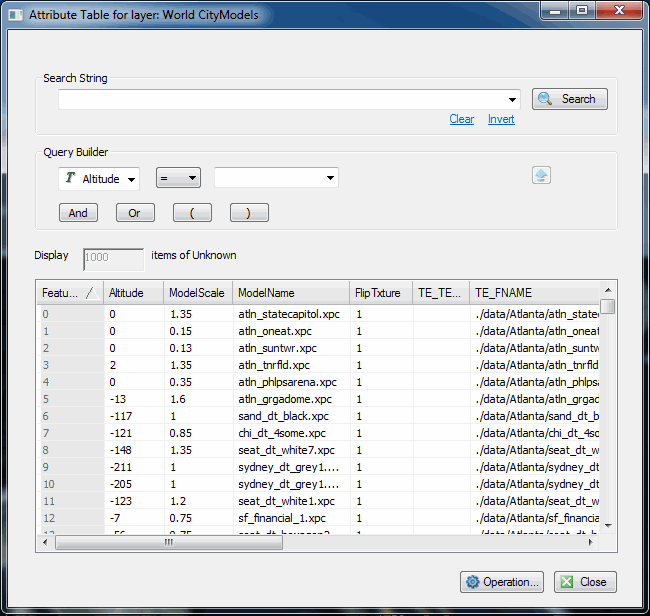
Attribute Table
The Attribute Table enables you to search the layer attribute database files and display the results in the 3D Window. You can use this table to fine-tune the information that is displayed on the terrain or to create a new project layer or file based on the filtered layer. For example, you can display all towns in Western Europe, which have a population of 20,000.
Using the Attribute Table, you can easily edit the attribute values of multiple features without opening separate property sheets for each feature.
Search expressions are comprised of one or more conditions. A condition consists of an attribute, an operator and an attribute value.
There are three types of attributes:
§ String
§ Integer
§ Double
Each attribute type has its corresponding operators.
A search expression can consist of more than one condition. In this case, you need to insert a connector between the conditions to specify their relations. In addition to AND, you can use the OR, NOT and [] connectors to define the relations between conditions.
To search and perform operations by attribute:
1. In the Project Tree, select the required layer.
2. On the Feature Layer tab, in the Attributes group, click Attribute Table.
3. If you want to search for a previously-searched-for search expression, select one from the Search String dropdown list, and skip to step 6.
4. In the Query builder section, enter an attribute, condition, and value and click Insert String . The search expression is displayed in the Search String field.
Note: All attribute values are listed in the value dropdown list.
Note: If you want to clear the Search String field, click Clear.
5. If you want to include additional strings in your search expression, click one of the connector buttons:  and repeat step 4 for the next condition.
Search6. Click . Your search results are displayed in the search results list at the bottom of the page.
Note: A maximum of 1000 features are displayed initially. If the feature layer is a local layer, additional features can be listed by clicking More.
7. For each attribute value that you want to modify, double-click and type the required value.
8. Do any of the following:
§ To select a feature: in the Feature ID column, select the required Feature ID. Use CTRL-click or SHIFT-click to multi-select. This feature will remain selected even when the Attribute Table is closed.
§ To fly to a feature, right-click the feature’s row in the attribute table, and select Fly to selected item.
§ To edit a feature’s other attribute values and XY coordinates, right-click the feature’s row in the attribute table, and select Edit item. The feature’s property sheet is displayed.
§ To delete a feature, right-click the feature’s row in the attribute table, and select Remove items from layer.
§ To create a new layer composed only of the features which matched the search criteria: click the Operation button and select Add as New Layer Entry. The new layer is added to the Project Tree
§ To modify attribute properties: double-click the attribute value and modify as required. In the 3D Window, TerraExplorer flies from the current location directly to the selected feature.
§ To set the visibility of features based on their attribute values using the search expression entered in steps 3-5: click the Operation button and select Set Visibility by Attribute. The features matching the search criteria and their annotations are displayed on the terrain, and the Visibility property is saved in the project. If you want to redisplay all features, click the Operation button and select Clear Visibility by Attribute.
Note: All visibility by attribute settings are saved to Visibility property in the layer’s property sheet under both the Annotation and Feature tabs. You can also set visibility by attribute directly from the layer’s property sheet. See theVisibility property in "Polyline Property Sheet Parameters" and "Polygon Property Sheet Parameters" in the "Objects and Labels" chapter.
§ To save the filtered layer to a file: do the following:
i. Click the Operation button and select Save As.
ii. In the Save As dialog that is displayed, select the file type (.sqlite, .gdb, gpkg, .shp, .dxf, or .pdf).
iii. Browse to the required file directory, and type a file name.
iv. If you are saving the layer as an .sqlite, .gdb, .gpkg, or .pdf file, type a Layer name.
v. Click Save.
Editing features
You can edit feature attributes or position on the terrain.
Editing an individual feature in the 3D window
To edit a feature:
1. Select the feature. See "Selecting Features from the 3D Window" in this chapter for information.
2. In the feature’s property sheet, set its properties (X, Y, and MGRS) and feature attributes.
Note: Features have field attributes, only if the feature layers are loaded with attribute fields, such as "Country Population". If the layer does not contain attribute fields, or in the loading phase, you did not select any attribute field to load, no field attributes are listed in the property sheet.
3. Edit the polyline, polygon or point object. See "Editing Objects in the 3D Window" in the "Working with Objects" chapter.
4. If you want to undo/redo any edit action, on the top of the layer’s property sheet, click Undo  / Redo
  . Changes can be undone or redone, even after the property sheet is closed, and then reopened.
Editing multiple features' attributes
To edit selected features’ attributes:
1. Select the required features either by selecting them in the 3D Window or by spatial query. See "Selecting Features from the 3D Window" and "Spatial Queries" in this chapter for information.
2. On the Feature Layer tab, in the Edit group, click Editing and select Attributes. The Attribute Table for the selected layer opens with the selected features and their attributes displayed in the Search Results section.
Note: You can also click Attribute Table on the Feature Layer tab.
3. For each attribute value that you want to modify, double-click and type the required value.
Feature layer operations
The following feature layer operations are available:
§ Exporting Selected Features to a New File
§ Merging
§ Clipping
§ Cutting, Copying, and Pasting Features
Exporting selected features to a new file
To export selected features to a new layer:
1. Select the required features either by selecting them in the 3D Window or by spatial query. See "Selecting Features from the 3D Window" and "Spatial Queries" in this chapter for information.
2. On the Feature Layer tab, in the Load and Save group, click the arrow next to Save Layer and select Save Selected Features As. The Save As dialog is displayed.
3. Type a File name.
4. Select a file type (.sqlite, .gdb, .gpkg, .shp, .dxf, or .pdf).
5. If you are saving the layer as an .sqlite, .gdb, .gpkg, or .pdf file, type a Layer name.
6. Browse to the required Save location and click Save.
Adding a feature to a layer
To add a feature to a layer:
1. Select the layer.
2. On the Feature Layer tab, in the Edit group, click Add [Polyline, Point, or Polygon]. The [Polyline, Point or Text Label] property sheet opens. The geographic features that can be added depend on the type of feature layer.
3. Set the parameters of the geographic feature [polyline, point, or polygon].
4. In the 3D Window, place the object’s points by clicking in the desired location. You must place at least two points for a polyline and three points for a polygon. See "Editing Objects in the 3D Window" for information on editing feature objects.
5. Finish the object insertion by right-clicking.
6. Continue to edit the object’s parameters, and set the feature’s attribute values, or close the property sheet to finish the operation.
Deleting selected features
To delete selected features:
1. Select the required features either by selecting them in the 3D Window, by spatial query, or by using the Attribute table. See "Selecting Features from the 3D Window", "Spatial Queries", and "Using the Attribute Table Tool" in this chapter for information.
2. On the Feature Layer tab, in the Edit group, click Editing and select Delete.
Merging features
The Merge command combines features lying on the same plane from a single polyline or polygon layer into one feature. When merging overlapping polygons, a single part feature is created that is the union of the merged features. When non-overlapping polygons or polylines are merged, a multipart feature is created with one set of attributes.
To merge selected features:
1. Select the required features either by selecting them in the 3D Window or by spatial query. See "Selecting Features from the 3D Window" and "Spatial Queries" in this chapter for information.
Note: Only polylines and polygons can be merged.
2. On the Feature Layer tab, in the Edit group, click Editing and select Merge.
3. In the 3D Window, select the feature whose attributes should be used for the merged object by clicking it.
Clipping features
The Clip command creates a new feature by clipping away from a specified polygon or polygons the area that overlaps with the clip polygon. The polygons must all be from a single layer and lie on the same plane.
To clip a polygon:
1. Select the required polygons either by selecting them in the 3D Window or by spatial query. See "Selecting Features from the 3D Window" and "Spatial Queries" in this chapter for information.
2. On the Feature Layer tab, in the Edit group, click Editing and select Clip.
3. In the 3D Window, select the polygon to clip from the other polygons by clicking it.
Intersecting features
The Intersect command creates a new feature from the common areas of any two polygons. You choose which feature's attributes will be preserved during the operation. The polygons must all be from a single layer and lie on the same plane.
To create a polygon from the intersection of other polygons:
1. Select the required polygons either by selecting them in the 3D Window or by spatial query. See "Selecting Features from the 3D Window" and "Spatial Queries" in this chapter for information.
2. On the Feature Layer tab, in the Edit group, click Editing and select Intersect.
3. In the 3D Window, select the polygon that determines the attributes by clicking it.
Exploding features
A selected multi-part feature can be separated into its individual, component features using the Explode command.
To explode a multi-part feature:
1. Select the required multi-part feature. See "Selecting Features from the 3D Window" in this chapter for information.
2. If you want to separate all the features, on the Feature Layer tab, in the Edit group, click Editing and select Explode All.
3. If you want to separate out only specific features, do the following:
a. On the Feature Layer tab, in the Edit group, click Editing and select Explode.
b. In the 3D Window, select a feature from within the selected area that you want to separate out.
c. Repeat steps a and b for each object you want to separate.
Moving features from the 3D window
A single feature or multiple features can be moved in the 3D Window.
To move a feature(s):
1. Select the required features either by selecting them in the 3D Window or by spatial query. See "Selecting Features from the 3D Window" and "Spatial Queries" in this chapter for information.
2. If you selected a single feature, on the top bar of the object’s property sheet, click XY Plane  .
.
3. If you selected multiple features, right-click and select Move from the shortcut menu. The multi-edit property sheet opens.
4. In the 3D Window, place the cursor over the feature or the selection frame. The cursor changes to Move mode  .
.
5. Click the feature(s), and drag it to the required location in the XY Plane. Release the left mouse button to set the feature(s) at the current location.
Note: You can also move the feature(s) by modifying the coordinate information in the property sheet.
Cutting, copying, and pasting objects
You can copy or cut one or more objects in the 3D Window and paste them in another location. All cut/copied objects are placed in a buffer for future pasting, until new objects are copied/cut. Objects pasted from the Feature Layer Clipboard are pasted as new features in the selected layer. If you want to generate new objects, rather than features, you can instead paste the objects from the Home tab Clipboard.
Using advanced clipboard mechanisms, you can generate any 2D or 3D object based on the geometry of the objects in the clipboard (e.g., generate buildings according to properties of selected polygons). These objects can be saved either as a TerraExplorer group of objects or as a new feature layer (shapefile).
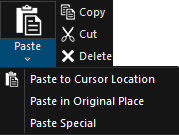
Copy Paste Ribbon Commands
Copying and Pasting Features
To copy and paste features:
1. On the Feature Layer tab, in the Selection group, toggle on Select Feature.
2. To copy: In the 3D Window, place the cursor over the required feature, and type CTRL + C.
Note: You can also select the feature, and use the ribbon commands on the Feature Layer tab or the right-click menu to copy and paste.
3. To paste:
§ To cursor location – Type CTRL + V. A copy of the feature is pasted in the current location of the cursor, and the cursor mode changes to the last positioning mode (i.e., XY, Z or XYZ Magnet) that you used, so you can drag the pasted feature to the required location. Click the left mouse button to set the pasted feature in its place. See "Changing the Position of an Object" in the "Working with Objects" chapter for information.
§ In original place – On the Home tab, in the Edit group, click the arrow below Paste, and then click Paste in Original Place.
Note: The copy paste function produces different results when the clipboard is accessed from the Home tab rather than the Feature Layer tab. See "Cutting, Copying, and Pasting Objects" in the "Working with Objects" chapter for more information about copying and pasting objects from the Home tab. Note that copying can be performed from one tab and pasting from the other, but that certain information will not be retained in the process, e.g., if you copy objects using the Home tab clipboard and paste them from the Feature Layer tab as features into a layer, only the geometry of the objects will be applied. Likewise, if you copy features from the Feature Layer tab and then paste them from the Home tab clipboard, they will be pasted as standard TerraExplorer objects that are not part of the copied layer and therefore do not include layer and attribute data.
4. If you want to generate a 2D or 3D object based on the geometry of the features in the clipboard, do the following:
a. Click the bottom half of the Paste button, and then click Paste Special. The Paste Special dialog is displayed.
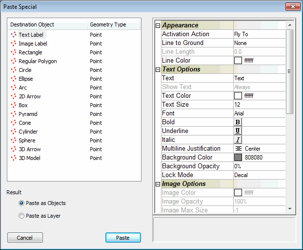
Paste Special Dialog
b. Select the Destination Object that you want to generate, and then modify its properties as required in the Property sheet.
c. Select whether to paste the object as an object or layer:
§ Paste as Objects – Create a group that contains an object for each copied feature object.
§ Paste as Layer – Create a new feature layer that contains a feature for each copied object.
d. Click Paste.
Cutting and Deleting Features
You can cut or delete one or more features.
Note: When you "cut" a feature in the 3D Window, the object is stored in the copy/cut buffer until a new copy or cut command is performed, so you can still restore it by performing the paste function. When you "delete" a feature, however, you cannot restore it.
To delete a feature object or objects:
1. Select the required feature/s either by selecting them in the 3D Window or by spatial query. A yellow frame surrounds each feature object. See "Selecting Features from the 3D Window" and "Spatial Queries" in this chapter for information.
2. On the Feature Layer tab, in the Clipboard group, click Delete.
OR
On the Feature Layer tab, in the Edit group, click Editing and select Delete.
To cut a feature:
1. Select the required feature/s either by selecting them in the 3D Window or by spatial query. A yellow frame surrounds each feature object. See "Selecting Features from the 3D Window" and "Spatial Queries" in this chapter for information.
2. On the Feature Layer tab, in the Clipboard group, click Cut.