Working with raster layers
Raster layers can be adjusted, processed, and prepared for distribution:
Moving and clipping a layer
An imagery or elevation layer is located on the terrain based on the geographic information it has, whether contained in the file, a reprojected value, or a manual input. You can modify the geographical location of a layer as well as clip a particular section of the layer, to display a subset of the image.
To change the geographical location of a layer:
§ After creating the imagery or elevation Layer, in the layer’s property sheet, in the "Imagery" or "Elevation" section respectively, update the Upper Left X, Upper Left Y, Lower Right X, and Lower Right Y values as required. See "Modifying raster layer parameters" in this chapter for information.
To clip a layer:
§ If you want to draw a polygon around the required subsection of the raster, do the following:
a. In the layer’s property sheet, in the Imagery section click Draw.
b. In the 3D Window, place the polygon points by clicking in the desired location. You must place at least three points.
c. Finish the polygon creation by right-clicking.
Note: When creating a filled polygon, the lines of the polygon should not overlap each other. This may result in an irregular fill pattern.
§ If you want to load a shapefile which contains the clip polygon you want to use, do the following:
a. In the layer’s property sheet, in the Imagery section click Load.
b. Browse to the required shapefile, and click Open.
Note: If you want to undo the clip or draw polygon action and restore the original raster, click Restore.
Modifying raster layer parameters
Imagery and elevation layer properties can be modified from the layer’s property sheet.
Note: If you want to undo/redo any edit action, on the top of the layer’s property sheet, click Undo ![]() / Redo
/ Redo ![]() . Changes can be undone or redone, even after the property sheet is closed, and then reopened.
. Changes can be undone or redone, even after the property sheet is closed, and then reopened.
|
Parameter |
Activity |
|
Appearance |
|
|
Line Color |
Select the outline color for the layer. Click the Edit button to open the Color dialog, or type the color code in hexadecimal BBGGRR format (B = Blue channel 00-ff, G = Green channel 00-ff, R = Red channel 00-ff). |
|
Line Opacity |
Enter the opacity for the layer’s outline. The opacity is defined as a percentage, where 100% is opaque and 0% is transparent. |
|
Fill Opacity |
Enter the opacity for the layer data. The opacity is defined as a percentage, where 100% is opaque and 0% is transparent. |
|
Line Style |
|
|
Line Width |
Enter the layer's line width, in the selected Line Width Units. |
|
Line Width Units |
Select Pixels or Meters/Feet. If Meters/Feet is selected, the unit displayed, meters or feet, depends on the setting in the View tab of the Options dialog. See "View" in the "Using TerraExplorer Options" chapter. |
|
Line Back Color |
Sets the layer's line back color. This field is only available when Altitude Method is set to On Terrain. Click the Edit button to open the Color dialog, or type the color code in hexadecimal BBGGRR format (B = Blue channel 00-ff, G = Green channel 00-ff, R = Red channel 00-ff). |
|
Line Back Opacity |
Enter the layer's line back opacity. This field is only available when Altitude Method is set to On Terrain. The opacity is defined as a percentage, where 100% is opaque and 0% is transparent. |
|
Visibility |
|
|
Tree Name |
Type the description or name of the layer. This text appears in the Project Tree as the name of the layer. |
|
Default Viewing Distance |
Determines the viewing distance of the camera from the layer. This distance is used as a stop mark for any "Fly-to" or "View Object" operation. It is also used when selecting to edit the layer from the Project Tree. When this value is set to the default of -1, TerraExplorer calculates and sets the ideal viewing distance for the layer based on its size. |
|
Activation Action |
Select the action to perform when selecting the layer from the Project Tree. |
|
Max. Visibility Distance |
Sets the distance from the camera at which the layer disappears. |
|
Min. Visibility Distance |
Sets the minimal distance from the camera below which the layer disappears. |
|
Points Position The parameters in this group are enabled only when Edit Nodes |
|
|
Selected Point |
Select the point to edit. The selected point is highlighted in the 3D Window. When you edit this point, the corresponding point on the base or the top of the polygon changes accordingly. |
|
Point X |
Enter the X-coordinate for the selected point. |
|
Point Y |
Enter the Y-coordinate for the selected point. |
|
Point MGRS |
The coordinates of the selected point in Military Grid Reference System (MGRS) coordinates. This field is only available if Show MGRS Coordinates was selected in the Options dialog. See "View" in the "Using TerraExplorer Options" chapter for more information. |
|
Imagery |
|
|
Imagery/Elevation File |
Type the full path of the file, or use the Edit button to browse to a supported imagery/elevation file or to open the Web map server browser dialog if loading a layer from a Web Map Server (WMS). |
|
Upper Left X |
Enter the X-coordinate of the layer top-left corner. |
|
Upper Left Y |
Enter the Y-coordinate of the layer top-left corner. |
|
Upper Left MGRS |
The coordinates of the layer top-left corner in Military Grid Reference System (MGRS) coordinates. This field is only available if Show MGRS Coordinates was selected in the Options dialog. See "View" in the "Using TerraExplorer Options" chapter for more information. |
|
Lower Right X |
Enter the X-coordinate of the layer bottom-right corner. |
|
Lower Right Y |
Enter the Y-coordinate of the layer bottom-right corner. |
|
Lower Right MGRS |
The coordinates of the layer bottom-right corner in Military Grid Reference System (MGRS) coordinates. This field is only available if Show MGRS Coordinates was selected in the Options dialog. See "View" in the "Using TerraExplorer Options" chapter for more information. |
|
Auto Refresh Interval |
The time interval, in seconds, for auto-refreshing the layer. The minimum interval is 10 seconds. |
|
Elevation Scale |
Change the elevation data to a new value. This feature enables you to adjust several elevation sources that are defined with reference to different baselines, such as different sea levels. The elevation data in the source file is changed to a new value where: New Value = Old Value * Scale Factor + Offset Value |
|
Elevation Offset |
Change the elevation data to a new value. This feature enables you to adjust several elevation sources that are defined with reference to different baselines, such as different sea levels. The elevation data in the source file is changed to a new value where: New Value = Old Value * Scale Factor + Offset Value |
|
Remove Null Value |
Select Yes to display the color or elevation data whose value is nullified. Select No to keep the selected value nullified. |
|
Null Value |
Nullify a color value in an imagery layer or an elevation value in an elevation layer: § Imagery Layer - Nullify a color value to make the underlying terrain visible in places that are colored with the nullified color value. Elevation Layer - Nullify an elevation value to cancel the value's elevation effect. |
|
Null Tolerance |
Enter the permissible deviation from the specified Null value when the color value is irregular. |
|
Draw Polygon |
Click the Draw button to clip a subsection of the raster. Place the polygon points in the 3D Window by clicking in the desired location. You must place at least three points. Finish the polygon creation by right-clicking. Note: When creating a filled polygon, the lines of the polygon should not overlap each other. This may result in an irregular fill pattern. |
|
Reset Polygon |
Click to restore the original raster. |
|
Import Polygon |
Click to import a shapefile which contains the clip polygon you want to use. |
|
Projection |
|
|
Reproject Source |
If you want to reproject the source’s geographic information from the source coordinate system to the terrain coordinate system, select Yes. |
|
Reproject Elevation |
Select the check box to reproject the layer’s elevation values to the terrain’s coordinate system. This option only applies when Altitude Method is set to Absolute. Geocentric layers are always reprojected. |
|
Description |
Free text describing the coordinate system. |
|
Coordinate System |
Click Set to open the Coordinate System dialog, and set the required coordinate system. See "Coordinate System Dialog" in the "Basic Concepts" chapter for information. |
|
General |
|
|
Message |
The message associated with the object. The number displayed is the number of the message. To create a new message, or update an existing message, open the Create Message dialog by clicking in this field and selecting Edit. See "Using the Create Message Dialog" in the "Working with Objects" chapter for more information. |
|
Tooltip |
Type a Tooltip text to appear when the mouse cursor is placed over the layer in the 3D Window. |
|
Timespan |
|
|
Start Time |
Click Edit and select the date and time when the layer should first become visible. |
|
End Time |
Click Edit and select the date and time when the layer should stop being visible. |
|
Order |
Determines the order of objects with On Terrain altitude method, from back to front. Objects with higher values are displayed on top of objects with lower values. |
Converting raster to MPT with resolution pyramid
Convert selected raster files, which do not include resolution levels or have an insufficient number of them, to stream-optimized MPT files with resolution pyramids.
To display a layer in different altitudes, TerraExplorer Pro requires a number of resolution levels per layer, which are also known as a resolution pyramid or a multi-resolution file. Without a resolution pyramid, the layer will not be displayed when attempting to zoom out from the original resolution level.
A layer source file may or may not include resolution levels or may have an insufficient number of them. In that case, TerraExplorer can generate a resolution pyramid for such sources. The resulting MPT file replaces the original layer source file and does not point to it.
Note: It is good practice to convert all layers in the project to MPT with a resolution pyramid.
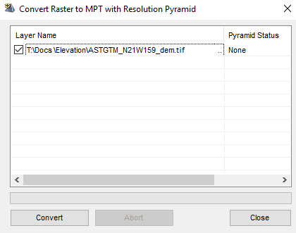
Convert Raster to MPT with Resolution Pyramid Dialog
To convert a raster layer to an MPT with a resolution pyramid:
1. In the Project Tree, select the layers that require a resolution pyramid.
2. On the Layers tab, in the Raster group, click Raster to MPT. The Convert Raster to MPT with Resolution Pyramid dialog is displayed.
3. Select the check boxes of the layers for which to create a resolution pyramid.
4. Click Convert. When the creation process is finished, the Pyramid Status column changes to "Done".
Note: If you want to cancel the resolution pyramid creation in the middle of the process, click Abort.
Uploading raster layers to SkylineGlobe Server
Raster layers can be uploaded to SkylineGlobe Server either by publishing the entire TerraExplorer project in which they are included (see "Publishing a Project to SkylineGlobe Server" in the "Working with SkylineGlobe Server" chapter) or by uploading individual layers.
To upload a layer:
§ In the Project Tree, right-click the required layer, and select Upload to SkylineGlobe from the shortcut menu. See "Uploading Layers to SkylineGlobe Server" in the "Working with SkylineGlobe Server" chapter for information.