Modifying Photo and Photo Collection Properties
Photo data can be viewed and modified in the photo collection property sheet and photo list. Information displayed in the property sheet refers to the collection that is currently selected in the collections list, while information in the photo list is specific to each photo.
Information about the photo collections and photos (e.g., coordinate system, sensor width, focal length, photo position information) is generally read from a loaded Excel or XML file that includes this information. These parameters can then be adjusted in the collection property sheet and photo list.
Properties can be edited even after aerotriangulation, up until the reconstruction step starts. When rebuilding, if any change was made to photo/collection properties, the build is restarted from pre-aerotriangulation.
To display and modify photo collection properties:
1. In the Project Tree, select the Photos group.
2. In the collection property sheet , modify the property values as required. See "Collection Property Sheet" in this chapter for more information.
To display and modify photo properties:
1. In the Project Tree, select the Photos group.
2. In the Photos list, select the required photos, and modify their properties as required. See "Photos List" in this chapter for information.
Note: You can also search the list for the required photos. See "Selecting Items Using the Item List" in the "Basic Concepts" chapter for information.
Collection Property Sheet
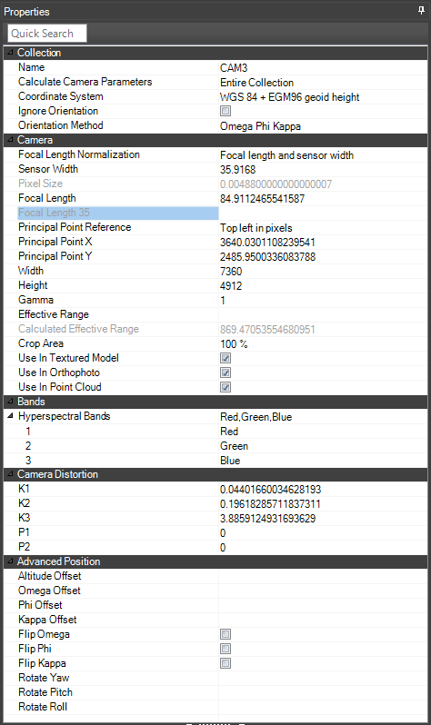
Note: If one or more of the camera properties that are used to set the focal length (These properties vary depending on the Focal Length Normalization property setting set in the Collection property sheet) is missing, an orange question mark ![]() is displayed next to the property.
is displayed next to the property.
|
Property |
Description |
|
Collection |
|
|
Name |
Name of the collection in the Photos list. |
|
Coordinate System |
Coordinate system of the collection. Click Select |
|
Orientation Method |
Select which system to use to set orientation: OPK (Omega, Phi, Kappa) or YPR (Yaw, Pitch, and Roll). This selection determines which fields are displayed in the Advanced Position section of the property sheet. |
|
Altitude Type |
When both relative and absolute altitude data were provided, this property sets the altitude method to be used by the collection. Select Relative to Terrain to place the collection at a specified altitude above the ground. Select Absolute to place the collection at a specified altitude above the terrain database vertical datum base ellipsoid. |
|
Relative Altitude |
If "Relative" was selected as the Altitude Type, this defines the altitude above the ground. |
|
Camera |
|
|
Focal Length Normalization |
Camera properties used to set the focal length. Select one of the following options: § Focal length and sensor width § Focal length and pixel size § Focal length 35 |
|
Sensor Width |
Size of the camera sensor in millimeters. |
|
Pixel Size |
Size of a physical pixel on the camera sensor in millimeters. |
|
Focal Length |
Focal length in millimeters. |
|
Focal Length 35 |
Equivalent focal length in millimeters for a 35 mm film camera. |
|
Principal Point Reference |
Origin and units of the principal point. Select one of the following: § Top left in pixels – Positive x-direction is to the right and positive y-direction is downwards. § Top left in mm – Positive x-direction is to the right and positive y-direction is downwards. § Center in pixels – Positive x-direction is to the right and positive y-direction is upwards. § Center in mm – Positive x-direction is to the right and positive y-direction is upwards. |
|
Principal Point X |
Principal point X value in pixels or mm according to principal point reference. |
|
Principal Point Y |
Principal point Y value in pixels or mm according to principal point reference. |
|
Width |
Width of photo in pixels. |
|
Height |
Height of photo in pixels. |
|
Gamma |
Brightness of the photo’s colors. The default value of 1 leaves the color unchanged. Values >1 brighten the colors, while values <1 darken them. |
|
Maximum distance from the camera position for which photo information is considered valid for the aerotriangulation. |
|
|
Calculated Effective Range |
Whenever the Effective Range parameter value is not provided, PhotoMesh calculates the maximum distance from the camera for which photo information is considered valid for the aerotriangulation, and then displays and uses this value. |
|
Crop Area |
Percentage of the photo to use in the project. Blurry or obstructed areas on the edges of a photo will be cropped based on this property value. |
|
Use in Textured Model |
Select the check box to include this collection in the textured model. |
|
Use in Orthophoto |
Select the check box to include this collection in the orthophoto. |
|
Use as Reference Only |
Select the check box to include this collection only in the reference project. See "Adding a Reference Project to Use in Aerotriangulation" in the "Control Points" chapter for information. |
|
Use in Point Cloud |
Select the check box to include this collection in the point cloud output. |
|
Bands – Multispectral Note: The band information is retrieved from the collection information in the photo list Excel or XML, the collectionProperties XML, or from the first photo in the collection. See "Loading a Photo List File" and "Loading Photo Files from Disk" in the "Photo Management" chapter. You can manually set the value for each band in the property sheet. |
|
|
Multispectral Bands |
Multispectral bands in the collection’s photos. These bands can be used in texturing the 3D model and in generating the orthophoto. See "Setting Advanced Reconstruction Parameters" in the "Building" chapter. |
|
1 |
Select the first band. |
|
2 |
Select the second band. |
|
3 |
Select the third band. |
|
Camera Distortion (Optional) Radial and tangential distortion calculated using the Brown-Conrady model. See here for more information. |
|
|
K1 |
Defines the 1st radial distortion coefficient. |
|
K2 |
Defines the 2nd radial distortion coefficient. |
|
K3 |
Defines the 3rd radial distortion coefficient. |
|
P1 |
Defines the 1st tangential distortion coefficient. |
|
P2 |
Defines the 2nd tangential distortion coefficient. |
|
Advanced Position (Either OPK or YPR offset and flip values will be displayed, depending on your selection above for Orientation Method) |
|
|
Altitude Offset |
Offset from the current altitude value. |
|
Omega Offset |
Offset in degrees along the Omega axis from the photo's provided angle. Applied before any additional rotation and prior to calculating position/orientation, this property helps correct orientation discrepancies between a camera and the plane on which it is mounted. |
|
Phi Offset |
Offset in degrees along the Phi axis from the photo's provided angle. Applied before any additional rotation and prior to calculating position/orientation, this property helps correct orientation discrepancies between a camera and the plane on which it is mounted. |
|
Kappa Offset |
Offset in degrees along the Kappa axis from the photo's provided angle. Applied before any additional rotation and prior to calculating position/orientation, this property helps correct orientation discrepancies between a camera and the plane on which it is mounted. |
|
Yaw Offset |
Offset in degrees along the Yaw axis from the photo's provided angle. Applied before any additional rotation and prior to calculating position/orientation, this property helps correct orientation discrepancies between a camera and the plane on which it is mounted. |
|
Pitch Offset |
Offset in degrees along the Pitch axis from the photo's provided angle. Applied before any additional rotation and prior to calculating position/orientation, this property helps correct orientation discrepancies between a camera and the plane on which it is mounted. |
|
Roll Offset |
Offset in degrees along the Roll axis from the photo's provided angle. Applied before any additional rotation and prior to calculating position/orientation, this property helps correct orientation discrepancies between a camera and the plane on which it is mounted. |
|
Flip Omega |
Flips the Omega axis. |
|
Flip Phi |
Flips the Phi axis. |
|
Flip Kappa |
Flips the Kappa axis. |
|
Rotate Yaw |
Additional rotation along the Yaw axis in degrees, that is performed in YPR order after the photos' OPK or YPR orientation and offsets were applied |
|
Rotate Pitch |
Additional rotation along the Pitch axis in degrees, that is performed in YPR order after the photos' OPK or YPR orientation and offsets were applied |
|
Rotate Roll |
Additional rotation along the Roll axis in degrees, that is performed in YPR order after the photos' OPK or YPR orientation and offsets were applied |
|
Note: The "Use build settings" option for the properties below sets the accuracy value based on the build settings for the project. For more information on this and other accuracy parameter options, see "Setting Advanced Aerotriangulation Parameters" in the "Building" chapter for information. |
|
|
Ignore Orientation |
Ignore the orientation value. |
|
Horizontal Accuracy Factor |
Weight to assign to the photos’ provided XY coordinates in determining the calculated XY values. This ranges from Very High - External AT (Factor = 100) to Unreliable (Factor = 0). |
|
Vertical Accuracy Factor |
Weight to assign to the photos’ provided altitude in determining the calculated altitude value. This ranges from Very High – External AT (Factor = 100) to Unreliable (Factor = 0). |
|
Focal Length Accuracy |
A percentage that indicates the allowable deviation from the provided focal length value when calculating the AT. This represents the accuracy of the provided focal length. This ranges from Use Input Value to Unreliable. |
|
Principal Point Accuracy |
A percentage that indicates the allowable deviation from the provided principal point when calculating the AT. This represents the accuracy of the provided principal point. This ranges from Use Input Value to Unreliable. |
|
Radial Accuracy |
Radial accuracy. It is generally recommended to select the "Standard" option. If your data was captured with a professional camera that automatically applied a radial distortion correction (i.e., the original distortion value is extremely accurate), select "Use input value". |
|
Tangential Accuracy |
Tangential accuracy. It is generally recommended to select the "Standard" option. If your data was captured with a professional camera that automatically applied a tangential distortion correction (i.e., the original distortion value is extremely accurate), select "Use input value". |
|
Calculate Camera Parameters |
Method of calculating the camera’s intrinsic parameters. § Use Build Settings – Use the method selected in the "Calculate Camera Parameters" AT build parameter. § Entire collection – Calculate the AT so that the camera intrinsic properties are the same for all photos in the collection. § Per photo – Calculate the camera intrinsics individually for each photo in the collection. Note: Parameters should be calculated per photo when not all of a collection’s photos were taken by the same physical camera with identical focal length and principal point. |
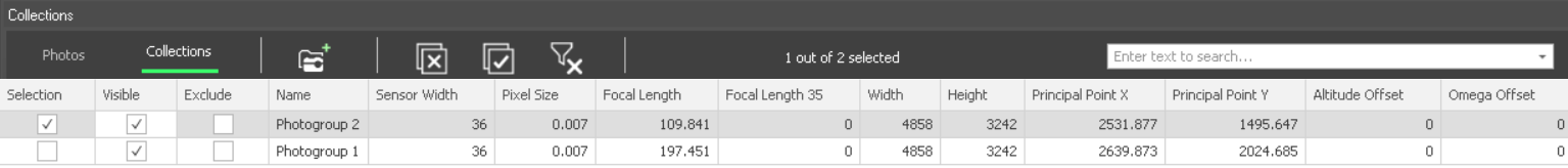
Collections List
In the Collections list, you can view collection properties. These properties can be edited in the Collection Property Sheet. See "About the Item List" in the "Using the Project Tree and Item List" chapter for information on working with the Collections list.
Collections List
To open the Collections list:
§ In the Project Tree, select the Photos group. The Photos list is displayed showing two tabs. Click the Collections tab. The Collections list lists all the collections in the project, with the following information/options:
|
Property |
Description |
|
Selection |
Select the collection on which to perform an action. |
|
Visible |
Select the check box to show the collection in the 3D Window. |
|
Exclude |
Select the check box to exclude the collection from the project. |
|
Name |
Name of the photo collection. |
|
Number of Photos |
Number of photos in the collection. |
|
Sensor Width |
Size of the camera sensor in millimeters. |
|
Pixel Size |
Size of a physical pixel on the camera sensor in millimeters. |
|
Focal Length |
Focal length in millimeters. |
|
Focal Length 35 |
Equivalent focal length in millimeters for a 35 mm film camera. |
|
Width |
Width of photos in pixels. |
|
Height |
Height of photos in pixels. |
|
Principal Point X |
Principal point X value in pixels or mm according to principal point reference. |
|
Principal Point Y |
Principal point Y value in pixels or mm according to principal point reference. |
|
Altitude Offset |
Offset from the current altitude value. |
|
Omega Offset |
Offset along the Omega axis in degrees. |
|
Phi Offset |
Offset along the Phi axis in degrees. |
|
Kappa Offset |
Offset along the Kappa axis in degrees. |
|
Horizontal Accuracy |
Accuracy of the photo’s provided X and Y coordinates. |
|
Vertical Accuracy |
Accuracy of the photo’s provided altitude. |
|
Focal Length Accuracy |
Accuracy of the camera’s inputted focal length. |
Photos List
In the Photos list, you can view and set photo properties, as well as set photo visibility and inclusion in the project. When calculated camera positions are displayed, you can also view calculated property information for a selected photo. See "About the Item List" in the "Using the Project Tree and Item List" chapter for information on working with the Photos list.
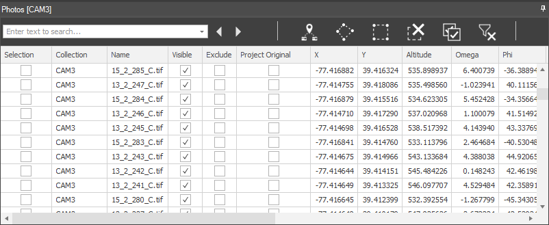
Photo List
To open the Photos list:
§ In the Project Tree, select the Photos group. The Photos list is displayed showing two tabs. Click the Photos list to view a list of all the photo files in the project, with the following information/options:
|
Property |
Description |
|
Selection |
Select the photos on which to perform an action, e.g., create tie point, show/hide camera symbol, exclude, delete. |
|
Collection |
Name of the photo collection (Read-only). |
|
Name |
Name of the photo. |
|
Visible |
Select the check box to show the photo in the 3D Window. |
|
Exclude |
Select the check box to exclude the photo from the project. This option is not available in Review mode. |
|
Project Original |
Select the check box to project the photo on the terrain in its provided camera position. A photo can be projected on the terrain to see if it fits the terrain imagery or to better understand the position of the photo. Only photos that have positioning (XY coordinates and altitude) and orientation (Omega, Phi, and Kappa) information can be projected. Note: Projecting multiple photos simultaneously can take several minutes. |
|
X |
East-west coordinate of the camera. (Required) |
|
Y |
North-south coordinate of the camera. (Required) |
|
Altitude |
Altitude of the camera in meters. (Required) |
|
Omega |
Omega Euler angle in degrees. |
|
Phi |
Phi Euler angle in degrees. |
|
Kappa |
Kappa Euler angle in degrees. |
|
Yaw |
Direction angle of the camera along the vertical axis relative to north. |
|
Pitch |
Tilt angle of the camera along its lateral axis relative to the horizon. |
|
Roll |
Roll angle of the camera along its longitudinal (front-to-back) axis. |
|
Path |
Full path of the photo. |
|
K1 |
Defines the 1st radial distortion coefficient. |
|
K2 |
Defines the 2nd radial distortion coefficient. |
|
K3 |
Defines the 3rd radial distortion coefficient. |
|
P1 |
Defines the 1st tangential distortion coefficient. |
|
P2 |
Defines the 2nd tangential distortion coefficient. |
|
Calculated Cameral Position Information (Additional columns) Note: If you want to view calculated information for a selected photo, click the Calculated button on the Tile tab. |
|
|
Project Calculated |
Select the check box to project the photo on the terrain in its calculated camera position. |
|
Median Error |
Median of the triangulation errors of all the features in the photo. The triangulation error is the distance, in pixels, for each of the features in the photo, between the automatically identified feature and its projected triangulation position. |
|
X Calculated |
Calculated east-west coordinate of the camera. |
|
Y Calculated |
Calculated north-south coordinate of the camera. |
|
Altitude Calculated |
Calculated altitude of the camera in meters. |
|
Omega Calculated |
Calculated Omega Euler angle in degrees. |
|
Phi Calculated |
Calculated Phi Euler angle in degrees. |
|
Kappa Calculated |
Calculated Kappa Euler angle in degrees. |
|
K1 Calculated |
Calculated 1st radial distortion coefficient. |
|
K2 Calculated |
Calculated 2nd radial distortion coefficient. |
|
K3 Calculated |
Calculated 3rd radial distortion coefficient. |
|
P1 Calculated |
Calculated 1st tangential distortion coefficient. |
|
P2 Calculated |
Calculated 2nd tangential distortion coefficient. |