Retouching a Mesh Layer
Mesh imperfections, such as bumps, irregular surfaces, or floating artifacts, can be flattened, filled, and cleaned up in PhotoMesh using the Manual Retouch tool. This tool allows you to mark the surfaces for flattening and floating artifacts for removal. The output of the Manual Retouch tool is a feature "retouch layer" with attribute information that defines what retouch action should be performed in each area: clean, flatten, and retexture. When rebuilding the project, PhotoMesh uses the manual retouch layer to add a set of constraints to the reconstruction algorithms. Most of the constraints defined apply to the mesh model, and the modified model is then retextured using the project’s photos. There is also an option in the Manual Retouch tool to set a specific file texture, e.g., water or grass, for a marked area, instead of basing texturing on the project’s photos.
You can run the manual retouch tool either on a 3D model (the reconstruction tile’s 3D textured model or the final 3DML) or on orthophoto output. All retouch operations are listed in the Manual Retouch list.
Note: After performing manual retouch operations, all affected tiles (e.g., tiles that now are intersected by the manual retouch polygon) require rebuilding from the model step. PhotoMesh will automatically determine what processing is required following the change, by rebuilding the project from "Auto".
To use the Manual Retouch tool:
Note: The shortcut keys only work when keyboard focus is on the retouch toolbox or the 3D Window.
1. Do any of the following:
§ In Mesh Mode:
· In the 3D Window, click the required reconstruction tile. Then on the Tile tab, in the Show group, toggle on Textured Model.
· In the Build Outputs list, select the 3DML output.
§ In Orthophoto Mode
· In the Build Outputs list, select the Orthophoto output.
2. On the Home tab, in the Add group, click the arrow under Retouch, and select Open Manual Retouch Toolbox. The Manual Retouch Toolbox is displayed.
Note: You can also open the Retouch tool by clicking Manual Retouch Tool from the Manual Retouch list. Alternatively, you can turn on global selection, and then select a manual retouch polygon/polyline in the 3D Window. See "Selecting Objects in the 3D Window" in the "Basic Concepts" chapter for information.
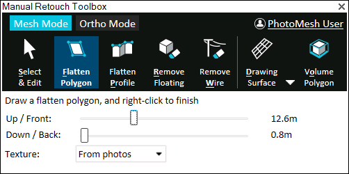
Manual Retouch
3. If you want to tag your edits with your name, click the user name link, and enter your user name. This information is saved in the layer’s username attribute. When multiple users work on the same retouch layer, this attribute enables you to identify the particular user that last worked on each retouch polygon.
4. Select a mode and perform your retouch operations:
§ Mesh Mode – Mark your edits on a 3D model output (the reconstruction tile’s 3D textured model or the final 3DML mesh model). See "Working in Mesh Mode" for more information.
§ Ortho Mode - – Mark your edits on the orthophoto output. See "Working in Orthophoto Mode" for more information.
Working in Mesh Mode
§ Creating a Surface on Which to Draw Your Retouch Polygon/Polyline
§ Performing a Retouch Operation
Creating a Surface on Which to Draw Your Retouch Polygon/Polyline
You can create a surface on which to draw your retouch polygon or polyline, e.g., for a model that is not flat or missing corners.
Do the following:
§ In the Manual Retouch Toolbox, click the arrow next to Drawing Surface (Shortcut key: d) and select one of the following options:
§ Show Last – Display the last surface that was created.
§ Edit – Open the surface property sheet to edit altitude, x, y, yaw, pitch, and roll properties, and use the toolbar to edit the surface in the 3D Window. See "Editing Polylines and Polygons" in this chapter for information.
· Click one of the other manual retouch commands and draw a polygon or polyline whose nodes are all lying in the same plane. Selecting Set Position Based on Mouse ![]() or Snap Based on Snapping Options
or Snap Based on Snapping Options ![]() in the polygon property sheet before drawing makes it easier to draw the polygons/polylines on a vertical plane.
in the polygon property sheet before drawing makes it easier to draw the polygons/polylines on a vertical plane.
§ Horizontal – The surface is aligned horizontally to the area under the cursor.
§ Vertical – The surface is aligned vertically to the area under the cursor.
§ 3 Points – The surface is aligned to the polygon created by the three points you draw.
Performing a Retouch Operation
A range of retouch operations are available so that you easily flatten, fill, or clean up any mesh imperfection:
§ Flatten polygon – Remove all elements inside a defined volume, and add a flat surface in the area of the 2D polygon, for e.g., filling holes and flattening walls. The area of the 2D polygon can be textured with any of the following:
§ From photos – Fill the polygon area using photos from the area.
§ Remove moving cars – Fill the polygon area using only photos from the area that don’t include moving cars. This option offers a solution to undesirable reconstruction effects that can occur when capturing an area with moving cars (e.g., a car that is partially sunk in the road), since only some of the captured photos included the cars, while others did not. It is recommended to individually retouch each car you want to remove by applying a unique polygon to it.
§ Single color – Fill the polygon area using a single color.
§ Texture pattern – Fill the polygon area with a water or grass texture.
§ Flatten profile – Create multiple flatten polygons by defining a profile line (usually on a roof top) and the base elevation. A flatten polygon is created for each segment of the profile line (from the line to the base elevation). This method is useful for creating retouch polygons in hard to access places, e.g., between buildings.
§ Remove floating – Remove all elements inside a defined volume. This option is generally used to remove floating elements that aren’t connected to the ground.
§ Remove wire – Remove thin elements such as power lines by drawing a polyline that marks the wire to be removed. A separate floating polygon is created for each segment of the polyline.
To perform a retouch operation:
1. Select one of the retouch operations in the Manual Retouch Toolbox, and then do the following:
§ Flatten polygon (Shortcut key: f)
i. Set a buffer for the retouch polygon upwards or frontwards and downwards or backwards in the direction of the polygon’s normal, slide the Up/Front buffer and Down/Back buffer sliders. If a polygon’s elevation angle to the ground is less than 20 degrees, the polygon is extruded vertically. If the polygon points were created in a clockwise orientation, then the front is the side facing the user.
ii. Select one of the fill options: From photos, Remove moving cars, Single color, or Texture pattern.
iii. For Single color fill, select the color to use. For Texture pattern fill, select a Texture pattern, and enter a value for the texture tile size.
iv. Draw a polygon around the area for flattening. Right-click to complete.
§ Flatten profile (Shortcut key: p)
i. Set a buffer for the retouch polygon upwards or frontwards and downwards or backwards in the direction of the polygon’s normal, slide the Up/Front buffer and Down/Back buffer sliders. If a polygon’s elevation angle to the ground is less than 20 degrees, the polygon is extruded vertically. If the polygon points were created in a clockwise orientation, then the front is the side facing the user.
ii. Draw the profile line, and then right-click to complete. Then click on the model to define the model's base elevation. A flatten polygon is created for each segment of the profile line (from the line to the base elevation).
§ Remove floating (Shortcut key: r)
i. Click any point on the floating artifact. PhotoMesh automatically creates a polygon that includes the selected point.
ii. Set a buffer for the retouch polygon upwards or frontwards and downwards or backwards in the direction of the polygon’s normal, slide the Up/Front buffer and Down/Back buffer sliders. If a polygon’s elevation angle to the ground is less than 20 degrees, the polygon is extruded vertically. If the polygon points were created in a clockwise orientation, then the front is the side facing the user.
§ Remove wire (Shortcut key: w)
i. To set a buffer for the retouch polyline upwards or frontwards and downwards or backwards in the direction of the polyline’s normal, slide the Front buffer and Back buffer sliders. If a polyline's elevation angle to the ground is less than 20 degrees, the polyline is extruded vertically. If the polyline points were created in a clockwise orientation, then the front is the side facing the user.
ii. Draw a polyline along the wire to remove, and then right-click to complete.
2. To select the polygon/polyline for editing after it is drawn, click Select and Edit (Shortcut key: s), and then select the retouch object for editing or right-click it in the Manual Retouch list, and select Edit. When editing a drawn polyline and changing the extrusion length, only the selected line segment is modified. See "Editing Polylines and Polygons" in this chapter for information.
3. To select how to display all manual retouch polygons, click the Volume icon (Shortcut key: o):
§ Volume Colorize – Mark the area for retouching by colorizing all parts of the mesh contained within the extruded polygon.
§ Volume Polygon – Mark the area for retouching by displaying 3D polygons based on the extruded polygon.
§ Volume No – Mark the area for retouching only with a 2D polygon.
Working in Ortho Mode
The following retouch operations are available in Ortho mode:
§ Clean Cars – Remove all elements inside a defined area, and texture the drawn polygon area using only photos from the area that don’t include moving cars. This option offers a solution to undesirable effects in the reconstruction (e.g., a car that is partially sunk in the road) that can occur when capturing an area with moving cars, since only some of the captured photos included the cars, while others did not. It is recommended to individually retouch each car you want to remove by applying a unique polygon to it.
§ Clean Edges – Remove artifacts along the edges of a model.
§ Import Layer – Import a polyline or polygon feature layer with retouch polylines/polygons for cleaning edges or cars. The following layer formats are supported: .shp, sqlite, and gpkg.
To perform a retouch operation in Ortho mode:
1. Select one of the retouch operations in the Manual Retouch Toolbox, and then do any of the following:
§ Clean Cars (Shortcut key: c)
i. Draw a polygon around the area that you want to clean.
ii. Right-click to complete. The buffers are automatically set to 10 meters above/below the surface.
§ Clean Edges (Shortcut key: e)
i. Set a buffer for the retouch polygon upwards or frontwards and downwards or backwards in the direction of the polygon’s normal, slide the Up/Front buffer and Down/Back buffer sliders. If a polygon’s elevation angle to the ground is less than 20 degrees, the polygon is extruded vertically. If the polygon points were created in a clockwise orientation, then the front is the side facing the user.
ii. Draw a polyline along the edge you want to clean. Right-click to complete. A polygon is generated with the base line on the ortho surface and the top line, one meter above the surface. All artifacts with normal vertical to the polygon are cleaned.
§ Import Layer (Shortcut key: i)
i. Click Import Layer, and then Browse, and browse to the required layer. The following layer formats are supported: .shp, sqlite, and gpkg. The retouch polygons included in the layer are added to the Manual Retouch list.
2. To select how to display the drawn polygon, click the Volume icon (Shortcut key: o):
§ Volume Colorize – Mark the area for retouching by colorizing all parts of the mesh contained within the extruded polygon.
§ Volume Polygon – Mark the area for retouching by displaying 3D polygons based on the extruded polygon.
§ Volume No – Mark the area for retouching only with a 2D polygon.
3. To adjust the length to extrude the retouch polygon upwards or frontwards and downwards or backwards in the direction of the polygon’s normal, select the polygon and in the Manual Retouch Toolbox, slide the Front buffer and Back buffer sliders. If a polygon’s elevation angle to the ground is less than 20 degrees, the polygon is extruded vertically. If the polygon points were created in a clockwise orientation, then the front is the side facing the user.
4. To select the polygon for editing after it is drawn, click Select and Edit (Shortcut key: s), and then select the retouch object for editing. Use the mini toolbar to edit the polygon. See "Editing Polylines and Polygons" in this chapter for information. You can also view and edit the manual retouch object’s properties in the Manual Retouch list. See "Modifying Retouch Objects" in this chapter for information.
Modifying Retouch Objects
All retouch operations can be viewed and edited from the Manual Retouch list. See "Selecting Items Using the Item List" in the "Using the Project Tree and Item List" chapter for more information.
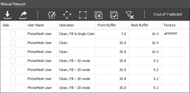
Manual Retouch List
To modify a retouch operation:
1. In the Project Tree, select the Manual Retouch group, and then in the Manual Retouch list, select the required polygon (i.e., row).
2. Perform any of the following actions:
§ Fly To/Jump To – Right-click the required row, and select Fly To/Jump To.
§ Delete Polygon – Right-click the required row, and select Delete.
§ Edit Polygon – Right-click the required row, and select Edit. The retouch polygon is selected in the 3D Window and a mini toolbar is displayed. See "Editing Polylines and Polygons" and "Marking a Mesh Layer for Retouching" in this chapter for information on modifying the polygon shape/position and properties. Some properties can be modified directly in the Manual Retouch list.
Exporting and Importing a Retouch Layer
You can export retouch layers with selected retouch polygons to an SQLite file. The layer can be modified in TerraExplorer and reimported to PhotoMesh.
In Ortho mode, you can also import a polyline or polygon feature layer with retouch polylines/polygons for cleaning edges or cars, in shp, sqlite, and gpkg formats. See "Working in Ortho Mode" in this chapter for more information.
To export a retouch layer:
1. In the Project Tree, select the Manual Retouch group, and then in the Manual Retouch list, select the retouch polygons that you want to export, and click Export ![]() . The Export Manual Retouch Objects dialog is displayed.
. The Export Manual Retouch Objects dialog is displayed.
2. Browse to the location where you want to save the layer, and click Save. The layer is exported with the selected retouch polygons as an SQLite file.
3. Browse to the required folder, and click Save.
To import a retouch layer:
1. On the Home tab, in the Add group, open the Retouch dropdown, and select Import Manual Retouch. The Import Manual Retouch Objects dialog is displayed.
2. Browse to the required SQLite file, and click Open. The layer is imported to the project.