Setting Build Steps, Parameters and Outputs
Before PhotoMesh can build the project, build steps, project parameters and project outputs are set in the Build Parameters dialog, using either a simplified view, or an advanced view that enables manual setting of relevant parameters. The simplified view consolidates all the main settings under a single tab ("Build Settings").
When using the advanced settings, you can select from a list of Build Presets that make it easy to automatically set the required parameters to generate the optimum output for the project’s data as well as to share user-defined build settings between projects. Presets only include changes from the default settings. See "Working with Presets" in this chapter for information.
If you want to manually set the AT and reconstruction settings, click the Aerotriangulation and Reconstruction tabs. See "Setting Advanced Aerotriangulation Parameters" and "Setting Advanced Reconstruction Parameters" in this chapter.
To set build steps, parameters, and outputs:
1. On the Home tab, in the Process group, click Build. The Build Parameters dialog is displayed.
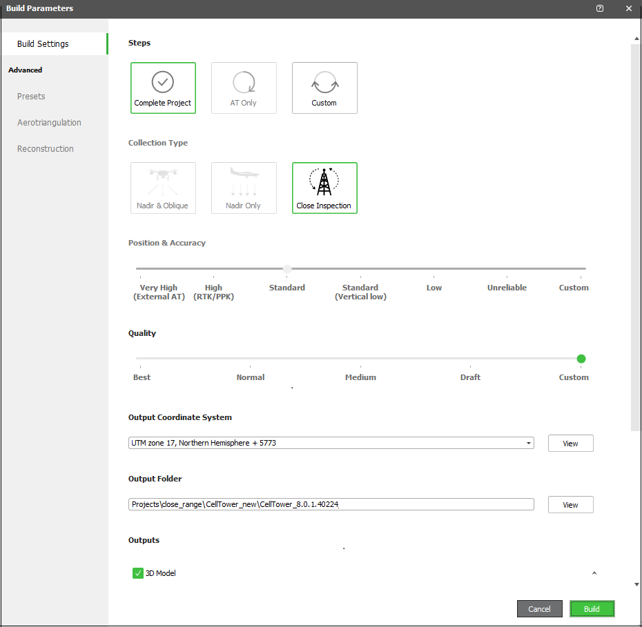
Build Parameters Dialog
2. Select the Build Steps to perform:
§ AT Only – Perform only AT so you can review results before proceeding with the rest of the build to ensure a precise AT which includes all project’s photos that intersect with the AT area. When an AT Only build is performed and then repeated following project adjustments, PhotoMesh determines precisely which tiles and which specific AT sub-processes were affected by the modification of properties or control points, enabling a much lighter and faster AT process.
§ Custom – Perform selected build steps. To select the steps:
i. In the Start From field, select the step from which you want to start the build. Select "Auto" to have PhotoMesh automatically determine what processing must be performed to complete the project, avoiding unnecessary rebuilding. E.g., when rebuilding a project after modifying a water polygon, only affected tiles are rebuilt from the point cloud step. Similarly, when rebuilding after reimporting exported models, only affected tiles are rebuilt, either from the texturing step, if just models were imported, or from the output step, if both models and textures were imported.
ii. In the Build Until field, select the step until which you want to build.
3. Select the Collection Type. This determines what project presets are set to achieve optimum output for the project’s data.
§ Nadir & Oblique – For photo collections with vertical and diagonal perspectives. PhotoMesh performs a full 3D reconstruction of terrain and surface areas.
§ Nadir Only – For photo collections with vertical perspective only. PhotoMesh reconstructs the terrain and textures the horizontal surfaces. PhotoMesh increases verticality of above ground features for an improved 3D model and True Ortho.
§ Close Inspection – For projects with a single object captured from all perspectives. PhotoMesh focuses on the foreground object to achieve best image correlation relative to the close-range object and optimizes 3D reconstruction for modeling of thin features and complex geometry.
4. Set the Position & Accuracy:
Note: The accuracy of each individual collection's position and orientation data is set in the collection's property sheet in the Accuracy section. There, you have the option to either input custom values or to select the "Use build settings" alternative to apply the general accuracy settings set in this dialog. If some collections have custom settings, a notification will display in this dialog informing you of this.
§ Very High (External AT) - PhotoMesh assigns a very strong weight to provided camera positioning (AT Result) when performing aerotriangulation. This option is recommended when reliable AT data in a Cartesian coordinate system, such as ENU or ECEF, is added to PM from other AT systems, e.g., Inpho and Bingo.
Note: AT data in a projected coordinate system such as UTM may be unreliable either due to earth curvature or earth curvature corrections performed in the other system. This is particularly true for datasets that contain oblique photos or large frames, or cover a large geographic area. For data of this type, aerotriangulation should be re-performed in PhotoMesh, i.e., use the High Accuracy option.
§ High (RTK/PPK) - PhotoMesh assigns a strong weight to provided camera positioning when performing aerotriangulation. If the inputted camera positions are inaccurate or inconsistent with any provided control points, it may be advisable to use the Standard GPS option. This option is recommended for collections captured by professional systems with accurate positioning and orientation information (e.g., using DGPS and INS).
§ Standard - PhotoMesh assigns a moderate weight to provided camera positioning. This option is recommended for collections using standard GPS with or without orientation information (e.g., standard drones such as those produced by DJI).
§ Standard (Vertical Low) - PhotoMesh assigns a moderate weight to provided camera horizontal positioning and a low weight to the camera’s vertical positioning. This option is recommended for use with photo collections captured in flights that involve reinitialization of the drone's GPS system due to battery changes.
§ Low – PhotoMesh assigns a low weight to provided camera positioning data. This option is recommended for collections whose GPS accuracy is compromised due to factors like weather conditions or varying elevation.
§ Unreliable – PhotoMesh performs a robust calculation of positioning and orientation information and camera parameters. This option is recommended when the difference between the input position and the actual position may be greater than 50m. In most cases this is caused by a lag between the acquisition of the positioning information and the photo capture time, or when multiple collections are captured at different times with inaccurate positioning hardware.
§ Custom –The level will be automatically set to Custom if custom accuracy settings were set on the Advanced - Aerotriangulation tab.
5. Set the Output Quality level of the point cloud, mesh model, and texture. Click Draft mode for faster processing and low quality outputs. The level will be automatically set to Custom if custom Quality and Performance settings were set on the Advanced - Reconstruction tab.
6. Set the project’s Output Coordinate System to which the project data should be reprojected. Select the Custom option to create a new custom coordinate system. See "Coordinate System" in the "Basic Concepts" chapter for more information. Click View to view the full Well-Known Text (WKT) for the coordinate system.
Note: 3D Tiles output is always produced in ECEF coordinate system and SLPK (I3S) output in WGS84 coordinate system with EGM96 vertical datum, regardless of the coordinate system selected here.
Note: All outputs are saved to the output folder, with a WKT to identify the output coordinate system that was selected in this parameter and special WKT’s for the coordinate systems of the 3D Tiles and SLPK (I3S) output (Output-WKT_Cesium.txt and WKT_I3S.txt).
7. The Output Folder is automatically populated with the path set for the project folder when creating a project. See "Creating and Opening a PhotoMesh Project" in the "Project Management" chapter for information. Click View to open the output folder in your File Explorer.
8. Select the required Output Formats:
Note: The available output formats vary depending on your license level. Contact Skyline Support for more information.
|
3D Model |
To generate 3D model output: 1. Select 3D Model. 2. Select all required 3D Mesh output formats: § 3DML – Stream-optimized, high-resolution 3D Mesh Layer database for loading directly into TerraExplorer and streaming with SkylineGlobe Server. § 3D Tiles – 3D Tiles streamline the delivery of large 3D datasets by organizing them into a multi-resolution format, using GLB to store the actual model data for streaming to Cesium clients. PhotoMesh supports version 1.0 of 3D Tiles and 2.0 of GLB. If you want to reproject the elevation values to ellipsoid (as required by the Cesium 3D Tiles standard) for compatibility with terrain that uses ellipsoid elevation, select Reproject to ellipsoid. This option should only be selected for terrain providers that use TRUE ellipsoid elevation. Note: Some applications use a TerrainProvider and other data with geoid elevation values even though they are declared as ellipsoid when delivered to Cesium. Thus, they are actually compatible without reprojection. Note: PhotoMesh outputs can easily be published to Cesium viewers by publishing the resulting 3DML to SGS. SGS will then make them available to TerraExplorer clients as 3DML as well as to Cesium by converting them on-the-fly to 3D Tiles. Use the 3D tiles output if you need to produce a full 3D Tiles output for a non-SGS web-server. § o3DML – 3D Tiles-based, hierarchically structured format designed for streaming and rendering massive 3D geospatial content. The Open3DML format packages all the mesh data files, with their full paths and names as unique IDs, within a single SQLite database table, that can be easily copied and managed. § OSGB – Multi resolution textured model for use in OpenSceneGraph. The file pyramid \p-00000.osgb is the root of the hierarchy that can be used to load all data. § DAE – Textured Collada model per reconstruction tile. § OBJ – Textured OBJ model per reconstruction tile. Note: If you want to reference the DAE/OBJ model’s coordinates to the project’s center, select Center pivot to project. This setting improves the stability of 3D model display in 3rd party viewers that are limited regarding display of large coordinates. This option does not need to be selected for OSGB since OSGB models’ coordinates are by default referenced to the project center. When selected, only DAE, OBJ, and OSGB can be produced. If you want to set a custom pivot, click More Options § SLPK (I3S) – Compressed package of ESRI's Indexed 3D Scene (I3S) Layers delivery format used to stream very large 3D geospatial datasets to mobile, web and desktop clients. SLPK v1.7 is generated. |
|
Point Cloud |
LiDAR LAS file with X,Y,Z position and color information for each point of the point cloud To generate point cloud output: 1. Select Point Cloud. 2. Select one of the following options: § Sampled refined 3D model – To create a point cloud by sampling the final textured model. Then in the Resolution field, enter the density for sampling the model. § Points from photo correlation - To generate a point cloud based on the correlation of points in the photos. 3. Select a format: LAS or LAZ. 4. Type a resolution in meters per pixel. |
|
Orthophoto |
True-orthophoto created from the resulting textured mesh in GeoTiff format. To generate: 1. Select Orthophoto. 2. Set the following properties: § Resolution – The raster resolution in meters per pixel. Select Auto to have PhotoMesh automatically select the optimal resolution based on the inputted data. § Image Quality – Select the check box to compress the orthophoto output, and then enter a JPEG compression level (0-100%). Select 99% to apply an LZW lossless compression. § Tile Size – Set the maximum tile size in pixels. Only values between 1000-40000 are accepted. § Overlap Between Tiles – Overlap in pixels between tiles. § Texture Blending – Determines whether to use data blended from multiple photos in texturing the orthophoto, or only data from the optimal photo. Select Auto to base this setting on Photo Priority, where "Nadir Direction" will set blending to No, and "Used in Reconstruction" will set blending to Yes. Select No if blending results in ghosting artifacts. § Photo Priority – Determines what type of photo is preferred when selecting the optimal photo for texturing the orthophoto. Select "Nadir Direction" to give priority to photos photographed from above. This option is recommended to avoid objects such as trees being textured from multiple photos photographed from different directions. Select "Used in Reconstruction" to give priority to the photo used to reconstruct the mesh for this area. This option is recommended when there are moving objects in the photos, to avoid having parts of objects appear in different areas of the orthophoto. § No-Data Color – Determines the color to assign to areas of the orthophoto for which there is no data or which are outside the reconstruction area. § Bands and Collections – Click the More Options § Tile Grid Origin – Set the X and Y coordinates of the origin of the tile grid in the output coordinate system. This allows you to set a common grid for multiple projects. Select Auto to have PhotoMesh automatically select the optimal grid origin based on the inputted data. |
|
DSM (Digital Surface Model) |
Elevation model in GeoTiff format that includes all elevation data, including buildings and reconstructed objects in the mesh. To generate: 1. Select DSM. 2. Enter the following values: § Resolution – The raster resolution in meters per pixel. Select Auto to have PhotoMesh automatically select the optimal resolution based on the inputted data. § Tile Size – Set the maximum tile size in pixels. Only values between 1000-40000 are accepted. § Overlap Between Tiles – Overlap in pixels between tiles. § Tile Grid Origin – Set the X and Y coordinates of the origin of the tile grid in the output coordinate system. This allows you to set a common grid for several projects. Select Auto to have PhotoMesh automatically select the optimal grid origin based on the inputted data. |
|
DTM (Digital Terrain Model) |
An elevation model that represents the bare ground surface without any objects such as plants and buildings. To generate: 1. Select DTM. 2. Enter the Resolution – The raster resolution in meters per pixel. Select Auto to have PhotoMesh automatically select the optimal resolution based on the inputted data. |
3. Click Build. The New build description dialog is displayed. Enter a build name and description and click Ok. The PhotoMesh Build Manager is displayed.
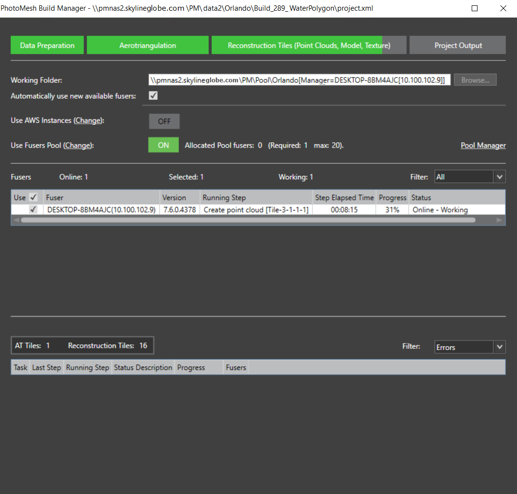
PhotoMesh Build Manager – Starting a Build
4. If you want to change the working folder, in the Working Folder field, click Browse and in the dialog that opens browse to the required folder. See "Setting the Working Folder (on the Master Computer)" in the "Fusers" chapter for information.
5. If you want PhotoMesh to automatically use any new fusers that connect to the project’s working folder, select Automatically use new available fusers. See "Using Fusers" in the "Fusers" chapter for information.
Note: This setting should generally be selected when using AWS and pool fusers.
6. If you want to use AWS fusers, toggle on Use AWS Instances. See "Using Amazon Web Services (AWS) Fusers" in the "Fusers" chapter for information.
7. If you want to use pool fusers, toggle on Use Fusers Pool, and enter the required information. See "Using a Fusers Pool" in this chapter for information
8. Select the required fusers. See "Fuser Management (on the Master computer)" in the "Fusers" chapter and "Monitoring a Build" in this chapter for more information on fusers.
Note: If there are currently no available fusers, a dialog is displayed asking if you want to start a local fuser. Click Yes to start a local fuser. Click No to start the build without adding a fuser; processing will begin automatically when fusers are added. If you want to cancel the build, click Cancel.
9. Click Build.