Working with Control Points
This section guides you through the various functionalities associated with control points within your project, including selecting, navigating to, editing, marking, and managing visibility and exclusion settings.
Selecting Control Points
Control points can be selected either in the 3D Window or from the Control and Tie Points list to perform various commands on them, e.g., hide, exclude, delete, export, or modify their properties.
To select a control point:
1. In the Project Panel, select the Control and Tie Points group.
2. In the 3D Window, click the control point you want to select, or select the control point(s) in the Control and Tie Points list. You can multi-select control points using the Control and Tie Points list commands.
Note: If you turned on global selection, you can select a control point in the 3D Window even without first selecting the Control and Tie Points group in the Project Panel as long as the control points are visible in the 3D Window.
See "Showing and Hiding Group Items" and "Selecting Items Using the Item List" and "Selecting Objects in the 3D Window" in the "Basic Concepts" chapter for information.
Navigating to a Control Point
To fly or jump to a control point:
1. Select the required control point. See "Selecting Control Points" in this chapter.
2. On the Control Point tab, in the Navigation group, click Fly To/ Jump To.
Editing Control Points
To edit a control point:
1. In the Project Panel, select the Control and Tie Points group, and then in the Control and Tie Points list, select the control point and edit its properties as required.
|
Parameter |
Definition |
|
General |
|
|
Name |
Name of the control point (as it appears in Quality Report, Control Point Editor, 3D Window, etc.). |
|
Point Type |
Select the point type: control point, tie point, or check point. |
|
Auto-GCP |
Automatically identify this control point’s marker in your photos and mark the photos in PhotoMesh accordingly. This will not override any manual marking of control points. See "Marking and Auto-Marking Control Points in Photos" step 9 in this chapter for more information. |
|
Exclude |
Select the check box to exclude the control point from the project. See "Excluding Control Points" in this chapter for more information. |
|
Visible |
Select the check box to make control point visible in project. See "Hiding Control Point Symbols" in this chapter for information. |
|
AT Tile |
AT Tile in which this control point is included. |
|
Sampled Photos |
Number of photos in which this control point was marked. If fewer than three photos were sampled, this field is marked in red (Read-only). |
|
Calculated Photos |
Number of photos in which the position of this control point was calculated (Read-only). |
|
Horizontal Accuracy (meters) |
Accuracy of the control point’s X and Y coordinates. The AT is adjusted to the control point within the specified accuracy margin of error. |
|
Vertical Accuracy (meters) |
Accuracy of the control point’s altitude. The AT is adjusted to the control point within the specified accuracy margin of error. |
|
Horizontal Error |
If the horizontal error is greater than the margin of error defined by the Horizontal Accuracy value, this field is marked in red (Read-only). |
|
Vertical Error |
If the vertical error is greater than the margin of error defined by the Vertical Accuracy value, this field is marked in red (Read-only). |
|
Sampling Error |
If the sampling error is greater than 1 pixel, this field is marked in red (Read-only). |
|
X |
East-west coordinate of the control point. |
|
Y |
North-south coordinate of the control point. |
|
Altitude |
Altitude of the control point in meters. |
|
Coordinate System |
Coordinate system of the control point. Click Select |
2. Save the project.
Marking and Auto-Marking Control Points in Photos
Control points are marked in photos using the Control Point Editor. Each control point should be marked in a few photos from each collection or photo direction. It is recommended to mark at least 10 photos for each control point.
In addition to the ribbon, the Control Point Editor includes:
§ A photo viewing window
§ A photos panel, which displays available photos as thumbnails or in table format with relevant information
§ A sampled photos panel that is gradually populated with thumbnails as you mark the control point in photos.
Note: In order to enable your ground control points to be fully utilized in the AT process, it is recommended to add at least 3-5 ground control points per AT tile:
· 1 control point – Only vertical adjustment is performed
· 2 control points - Vertical adjustment, scaling, and rotation are performed
· 3+ control points - Full transformation
Any control point marked in fewer than three photos will be marked in red in the Control Point list.
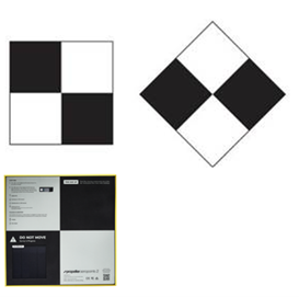
Auto-Marking Based on Control Point Marker Patterns: If your photos include control point marker patterns (e.g., checkerboard or cross patterns), PhotoMesh can automatically identify them and mark control points in photos based on them. It searches the photos for the chosen marker type based on the selected template, and links each detection to the nearest control point. If the marker includes an identifier, PhotoMesh will associate it with a specific control point instead.
If you manually mark a photo after enabling auto-marking, your manual marking takes precedence and overrides the automatic process for that control point. Automatically detected markers are added as regular markers only after aerotriangulation is performed. It is recommended to review the photos in Control Point Editor after performing aerotriangulation to see which were auto-marked with control points, so that you can add manual markers, if necessary.
Auto-Detect Based on First Manual Marking: After you manually mark a control point in a photo, PhotoMesh can auto-detect this control point in other photos. PhotoMesh scans up to 100 nearby photos, prioritized by proximity to the control point, and stops when it reaches the defined Maximum Detect Photos limit. Only photos with a confidence score of 98% or higher are considered, and previously marked photos are skipped in repeated runs.
This feature can be enabled globally through the PhotoMesh Options, triggering the search automatically after the first marking of each control point, or activated manually for individual control points through the Control Point Editor.
Control Point Markers
To mark a control point in photos:
1. If the control point was not already created, create the control point. See "Creating Ground Control Points" and "Creating Tie Points" in this chapter for information. The Control Point Editor is displayed.
2. If the control point was previously created, in the Project Panel, select the Control and Tie Points group, and then in the Control and Tie Points list, right-click the required control point, and select Edit. The Control Point Editor is displayed.
Note: If the Control Point Editor is already open, selecting a control point in the Control and Tie Points list opens that point in the Editor.
3. The Control Point Editor by default is docked in the right-hand side of the PhotoMesh window. If you want to undock it, click Toggle Editor Docking ![]() . Click again to redock the Editor.
. Click again to redock the Editor.
4. From the Photos filter, select which photos should be listed or displayed in the Photos panel:
§ All in frustum (Calculated) – All the photos whose calculated frustum intersects the control point.
§ All in range (Calculated) – All photos with the selected control point in their calculated range (according to their Effective Range).
§ All in frustum (Original) – All the photos whose frustum intersects the control point.
Note: For photos with positioning and orientation information, this is determined based on frustum, and for photos with only positioning, according to the effective range set (See "Collection Property Sheet" in the "Photo Management" chapter for information).
§ All in range (Original) – All photos with the selected control point in their range (according to their Effective Range).
Note: This option is only available if photos have positioning information.
§ All in project (Original) – All photos in project (up to 2000 photos).
§ Custom selection (Best) – All photos selected in the Photos list before creating the tie point from the Photo tab. See "Creating Tie Points in Selected Photos" in this chapter for more information.
5. Select a viewing format for the Photos panel:
§ ![]() – View as thumbnails
– View as thumbnails
§ ![]() – View in table format with information about distance, sampling error, etc. for each photo
– View in table format with information about distance, sampling error, etc. for each photo
6. If viewing the photos in table format, select the column by which you want to sort the table (in ascending order). Select the column a second time to switch to descending order. For filtering and advanced sorting options, see "Filtering Data in the Control Point Editor" in this chapter for information.
7. To view a photo using the Photo Viewer, select the photo from either the Photos panel or Sampled Photos panel, and click View in Photo Viewer ![]() . See "Viewing Photos in the Photo Viewer" in the "Preparing the Project" chapter. The Photo Viewer opens in the Control Point window. Click Back to GCP Editor to close the Photo Viewer and redisplay the editor.
. See "Viewing Photos in the Photo Viewer" in the "Preparing the Project" chapter. The Photo Viewer opens in the Control Point window. Click Back to GCP Editor to close the Photo Viewer and redisplay the editor.
8. In the Photos panel, select the photo on which you want to mark the position of the selected control point. The photo is displayed in the photo viewing window with a white cross hairs indicating the projected location of the control point that PhotoMesh automatically calculated. Type ‘n’ to select the next photo, or ‘p’ to select the previous one.
Note: Any photo thumbnails that are outside of the current build area are displayed in strikethrough font.
![]() Mark similar photosDetect after First MarkAuto 9. If - was enabled in PhotoMesh Options, PhotoMesh automatically scans up to 100 photos from the various collections to find photos with matches to the point marked in the first photo. If this option isn’t selected in PhotoMesh Options, you can can activate automatic detection by selecting in the Control Point Editor. The suggested photo matches are highlighted in purple in the Control Point Editor.
Mark similar photosDetect after First MarkAuto 9. If - was enabled in PhotoMesh Options, PhotoMesh automatically scans up to 100 photos from the various collections to find photos with matches to the point marked in the first photo. If this option isn’t selected in PhotoMesh Options, you can can activate automatic detection by selecting in the Control Point Editor. The suggested photo matches are highlighted in purple in the Control Point Editor.
10. Click any suggested photo to preview the auto-mark. Auto-marks appear in purple, and once accepted, they turn red. Click Accept ![]() to accept the suggested point for this photo. Click Accept All
to accept the suggested point for this photo. Click Accept All ![]() to accept suggested points for all photos.
to accept suggested points for all photos.
Note: Click Delete ![]() to remove the suggested point for this photo. Click Delete All
to remove the suggested point for this photo. Click Delete All ![]() to delete the suggested points for all photos.
to delete the suggested points for all photos.
11. To have PhotoMesh automatically identify control point marker patterns in your photos, linking each detection to the nearest control point or to a specific one if the pattern includes an identifier, do the following:
a. Click ![]() Pattern. The Auto-Mark Control Points dialog is displayed.
Pattern. The Auto-Mark Control Points dialog is displayed.
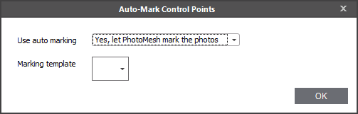
Auto-Mark Control Points Dialog
b. In the Use auto marking field, select Yes, let PhotoMesh mark the photos.
c. Select a Marking template. The template determines what marker type will be automatically identified by PhotoMesh as a control point, e.g., checkboard or cross. A dialog box is displayed asking whether you want to perform auto-marking of photos using the selected template for all the control points.
d. Click Yes if you want to auto-mark all the control points in all the photos. After selecting a control point for auto-marking, this setting can be overridden by manually marking this control point in one or more photos. If any of the photos a control point is found in were set for auto-marking, the Auto-GCP check box is selected for this control point in the Control and Tie Points list. The automatic markers are added as regular markers to the photos only after aerotriangulation is performed.
Note: It is recommended to review the photos in the Control Point Editor after performing aerotriangulation to see which were auto-marked with control points, so that you can add manual markers, if necessary.
12. If manually marking control points, find the correct position in the photo in which to mark the control point. Use the mouse to zoom in and out and pan in the photo or use the ribbon commands:
|
|
Zooms in. |
|
|
Zooms out |
|
|
Zoom in to the marked control point. This command is only available after a control point was marked in the photo. |
13. Click ![]() Sample in Photo, and then click on the photo where you want to set the position of the control point. You can also type ‘s’ on the keyboard to toggle between navigation and sampling modes. A red crosshairs is displayed where you clicked in the 3D Window and in the corresponding position on the photo thumbnail which is added to the "Sampled Photos" panel. The photo’s XY pixel coordinates are displayed in the Mark X and Mark Y fields on the Control Point Editor ribbon in the Control Point group. If the Photos panel is displayed in table format, the check box in the Marked column is selected (If displayed as thumbnails, a check is displayed on top of the reviewed photo). The following information is displayed in the photo viewing window:
Sample in Photo, and then click on the photo where you want to set the position of the control point. You can also type ‘s’ on the keyboard to toggle between navigation and sampling modes. A red crosshairs is displayed where you clicked in the 3D Window and in the corresponding position on the photo thumbnail which is added to the "Sampled Photos" panel. The photo’s XY pixel coordinates are displayed in the Mark X and Mark Y fields on the Control Point Editor ribbon in the Control Point group. If the Photos panel is displayed in table format, the check box in the Marked column is selected (If displayed as thumbnails, a check is displayed on top of the reviewed photo). The following information is displayed in the photo viewing window:
|
|
User sample for position of control point. |
|
|
Projected location of control point. |
|
|
Projected triangulation – Projection of the triangulation center (adaptive weighted median of all ray intersections) back to the photos. |
|
|
Sampling error - RMS |
|
Sampling Error - Photo |
Distance, in pixels, between the projected triangulation and the user sample in this photo. |
|
Sampling Errors - RMS |
Root mean square (RMS) of all distances, in pixels, between the projected triangulation and the user sample in all photos. |
|
Horizontal Error |
Horizontal distance, in meters, between the projected triangulation and the control point position. |
|
Vertical Error |
Vertical distance, in meters, between the projected triangulation and the control point position. |
14. If you want to modify the photo’s XY pixel coordinates, in the Control Point Editor, in the Mark X and Mark Y fields, type the required values.
15. If you want to clear the previously marked position of a control point, in the Control Point Editor, click ![]() Clear from Photo. The photo is removed from the "Sampled Photos" panel and the check is cleared from that photo thumbnail in the Photos panel.
Clear from Photo. The photo is removed from the "Sampled Photos" panel and the check is cleared from that photo thumbnail in the Photos panel.
Note: Only one position can be marked in each photo. If an additional position is marked, the previously marked position is automatically deleted and replaced by the new position.
16. Repeat steps 7-11 for each of the photos in which you want to mark the selected control point.
Filtering Data in the Control Point Editor
To filter control point lists in the Control Point Editor:
1. Point to the column by which you want to filter, and click the Filter icon ![]() . See "Filtering Data" and "Filter Editor" in the "Basic Concepts" chapter for information.
. See "Filtering Data" and "Filter Editor" in the "Basic Concepts" chapter for information.
2. Click Close. The applied filter(s) are listed at the bottom of the Photos panel, e.g., ![]() . Click X to remove a filter.
. Click X to remove a filter.
3. To access additional sorting commands, right-click any column header. Select any of the following commands:
|
Command |
Description |
|
Sort Ascending |
Sort all data in the table by this column in ascending order. |
|
Sort Descending |
Sort all data in the table by this column in ascending order. |
|
Clear All Sorting |
If multiple columns were sorted, this option is displayed to clear all. |
|
Group by This Column |
Group the data by this column. Note: If you want to clear the grouping, right click above the column headers, and select Clear Grouping. |
|
Show Group by Box |
Display boxes, above the photo table, indicating how the data is grouped in the table. Note: If you want to clear the Group by boxes, right click above the column headers, and select Hide Group by Box. |
|
Hide This Column |
Hide the selected column |
|
Column Chooser |
Customize which columns show in the table. Drag and drop columns to and from the Customization dialog. |
|
Best Fit |
Adjust the selected column’s width for the best fit for its contents. |
|
Best Fit (all columns) |
Adjust the all the table’s column widths for the overall best fit. |
|
Filter Editor |
Open the Filter Editor to edit the table filter. You can use the Filter Editor to add and remove conditions. A search expression can consist of more the one condition. In this case, you need to insert a connector between the conditions to specify their relations. In addition to AND, you can use the OR, NOT and [] connectors to define the relations between conditions. |
|
Show Find Panel |
Show a Find panel to search for a specific text. Note: To hide the Find panel, click the X next to it. it. |
|
Show Auto Filter Row |
Display a row with a filter option for each of the columns. |
Control Point Editor Keyboard Shortcuts
The following keyboard shortcuts are available:
|
Shortcut |
Description |
|
s |
Toggle between navigation and sampling modes. |
|
n |
Selects the next photo in the Photos panel and displays it in the photo viewing window. |
|
p |
Selects the previous photo in the Photos panel and displays it in the photo viewing window. |
|
N |
Selects the next control point in the Control Points table. |
|
P |
Selects the previous control point in the Control Points table. |
Hiding Control Point Symbols
To hide a control point symbol:
§ In the Project Panel, select the Control and Tie Points group, and then in the Control and Tie Points list, clear the control point's Visible check box.
Excluding Control Points
To exclude a control point from the project:
§ In the Project Panel, select the Control and Tie Points group, and then in the Control and Tie Points list, select the control point's Exclude check box.
Deleting Control Points
To delete a control point:
§ In the Project Panel, select the Control and Tie Points group, and then in the Control and Tie Points list, right-click the required control point, and select Delete.
Exporting Control Points
Control point data can be exported to a .gcp (text format) file. Auto-marked control point data is only exported in the .gcp file after aerotriangulation was performed. See "Marking Control Points in Photos" step 9 in this chapter for more information.
Note: All control points are exported in EGM96 geoid vertical coordinate system even if they were defined in "WGS84ELLIPSOID".
To export a project’s control point data:
1. On the Home tab, in the Add group, click the arrow under Control Points and select Export. The Export Control Points dialog is displayed.
2. Type a name for the .gcp (text format) file and browse to the required location in which to save the file.
3. Click OK.
Importing Control Points
Control point data can be imported in a simple text file, which contains headers (optional) and the name and position (XY coordinates and altitude) of each control point, using a consistent delimiter (e.g., comma or tab). E.g.,
x y z Name
0.39377912 79.64305958 79.6 Nadir434S72719X915341
0.39377912 79.64305958 79.6 Nadir434S72719X915341
0.39377912 79.64305958 79.6 Nadir434S72719X915341
To import:
1. On the Home tab, in the Add group, click the arrow under Control Points and select Import. The Import Control Point File dialog is displayed.
2. Browse to the required file and click Open. If your control point file is tab-delimited and in .gcp format, the control points are loaded into the project - skip to step 9. Otherwise, the Load Control Points from List dialog is displayed.
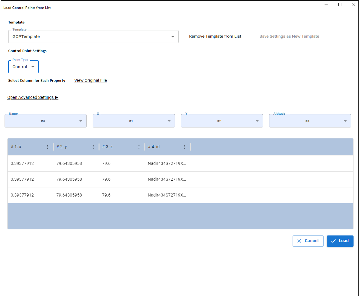
3. If you previously saved a template for mapping the txt file’s information to control point properties, select this template. To save a new mapping of txt file information and properties as a template, click Save Settings as New Template. Then in the dialog that is displayed, enter a name for the template, and click Save.
4. Select the control point type: Control, Check or Tie.
5. Click Open Advanced Settings to specify the location of headers and data within the control point file and choose the delimiter (e.g., comma, tab) used for parsing the file data. If there are no headers in your file, select the No Headers checkbox.
6. Map each property name (Name, X, Y, Altitude) to the correct column number in the control point file. If a template was applied, this may not be necessary. Use View Original File or the Preview Table to help verify mappings.
7. Click Load to load the control point information into PhotoMesh. The Coordinate System dialog is displayed.
8. Select the control points’ coordinate system, and click OK.
9. If the control point file includes only the terrain coordinates (and not the pixel positions in photos or an auto-marking template), the Auto-Mark Control Points dialog appears after import.
10. Select whether to auto-mark the control points in photos. If you select Yes, specify the marking template to use. See "Marking Control Points in Photos" step 9 in this chapter for more information.
Auto-Mark Control Points Dialog
11. Modify the control point properties as required, and then save the project.
Automated Control Point Import
PhotoMesh exposes a REST API that allows automated import of Ground Control Points. This API can be accessed using any REST client, such as Swagger UI, Postman, or similar tools.
Using Swagger:
1. Launch Swagger: Start PhotoMesh, and then from the Start page, open the Automation Dashboard and in the Project Queue section, click Reference Guide. See "Automation Dashboard" in the "Basic Concepts" chapter for information.
2. In Swagger, expand the ProjectApi section, and locate the ImportGCP method:
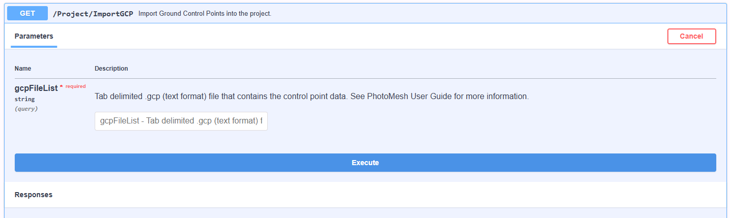
Swagger ImportGCP Method
3. Click Try it out, and then in the gcpFileList field, enter the import configuration as a JSON formatted string.
Note: Even though ImportGCP is a GET request, the import configuration is passed as a JSON string in the gcpFileList query parameter.
{
"headersAtRow": 1,
"dataAtRow": 2,
"headers": {
"Altitude": "#4",
"CollectionId": "#1",
"X": "#2",
"Y": "#3"
},
"coordinateSystem": "123",
"pointType": 1
}
4. Click Execute to start the automated import of the control points into the project.