.Creating a 3D Shape
To create a new 3D shape:
1. On the Objects tab, in the 3D Objects group, click 3D Shape, and then click the required shape. The 3D shape’s property sheet opens.
2. In the shape’s property sheet, set the object’s parameters.
3. If you want to position the 3D shape based on where the mouse is pointing in the 3D Window, on the top bar of the label’s property sheet, click Set Position Based on Mouse ![]() . See “Moving an Object Based on Where the Mouse is Pointing in the 3D Window” in the “Working with Objects” chapter for more information.
. See “Moving an Object Based on Where the Mouse is Pointing in the 3D Window” in the “Working with Objects” chapter for more information.
4. If you want to position the 3D shape based on where the mouse is pointing in the 3D Window and snap it to another object, on the top bar of the 3D shape’s property sheet, click Snap Based on Snapping Options ![]() . See “Moving an Object Based on Where the Mouse is Pointing in the 3D Window” and "Setting Snapping Options" in the “Working with Objects” chapter for more information.
. See “Moving an Object Based on Where the Mouse is Pointing in the 3D Window” and "Setting Snapping Options" in the “Working with Objects” chapter for more information.
5. If you want to position the 3D shape in the XY plane, on the top bar of the object’s property sheet, click XY Plane ![]() . See “Moving an Object in the XY Plane” in the “Working with Objects” chapter.
. See “Moving an Object in the XY Plane” in the “Working with Objects” chapter.
6. If you want to position the 3D shape in the Z plane, on the top bar of the object’s property sheet, click Z Plane ![]() . See “Moving an Object in the Z Plane” in the “Working with Objects” chapter for more information.
. See “Moving an Object in the Z Plane” in the “Working with Objects” chapter for more information.
7. With the cursor in the 3D Window, draw the shape required as described in the sections below:
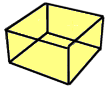
§ Box
§ Cylinder
§ Sphere
§ Cone
§ Pyramid
§ 3D Arrow
8. Edit the shape’s parameters in the 3D Window or using the property sheet. See “Editing Objects in the 3D Window” in the “Working with Objects” chapter for information. Close the property sheet to finish the operation.
Box
To draw a box:
1. Click the mouse to define the first corner of the box.
2. Drag the cursor to set the base of the box.
3. Once the base is set, click again to complete it.
4. Move the mouse up or down to define the height of the box.
5. Once the height is set, click again to complete the box.
Cylinder
To draw a cylinder:
1. Click the mouse to define the center point of the cylinder’s base.
2. Drag the cursor to set the base of the cylinder.
3. Once the base is set, click again to complete it.
4. Move the mouse up or down to define the height of the cylinder.
5. Once the height is set, click again to complete the cylinder.
Sphere
To draw a sphere:
Note: In the property sheet, you can choose to create a full sphere or just an upper or lower half of a sphere. When using half a sphere you can create it with or without a base.
1. Click the mouse to define the bottom center (pivot point) of the sphere.
2. Drag the cursor to define the radius of the sphere.
3. Once the radius is set, click again to complete the sphere.
Cone
To draw a cone:
1. Click the mouse to define the center point of the base circle.
2. Drag the cursor to define the radius of the base circle.
3. Once the base circle is set, click again to complete it.
4. Move the mouse up or down to define the height of the cone.
5. Once the height is set, click again to complete the cone.
Pyramid
To draw a pyramid:
1. Click the mouse to define the first base point.
2. Drag the cursor to set the base of the pyramid.
3. Once the base is set, click again to complete it.
4. Move the mouse up or down to define the height of the pyramid.
5. Once the height is set, click again to complete the pyramid.
3D Arrow
To draw a 3D arrow:
1. Click the mouse to define the pivot point of the 3D arrow.
2. Drag the cursor to set the length of the 3D arrow.
3. Once the base of the arrow is set, click again to complete it.
4. Move the mouse up or down to define the height of the arrow.
5. Once the height is set, click again to complete the 3D arrow.
3D Polygon
To draw a 3D polygon:
1. Click the mouse to define the first point of the 3D polygon.
2. Drag the cursor to the second point. Click again to set the second point.
3. Repeat the above step as many times as you like, until you have created your desired shape for the polygon. (The polygon still appears two-dimensional at this point.)
Note: When creating a 3D Polygon, the lines of the base polygon should not overlap each other. This may result in an irregular object.
4. Once the shape is established, click the right mouse button to complete it.
5. Move the mouse up or down to define the height of the 3D polygon.
6. Once the height is set, click again to complete the 3D polygon.


Examples of 3D Shape Objects
3D Shape Property Sheet Parameters
|
Object Parameter |
Activity |
|
Appearance |
|
|
Name |
Type the description or name of the shape. This text appears in the Project Tree as the name of the object. |
|
Activation Action |
Select the action to perform when selecting the shape from the Project Tree. |
|
Line Color |
Select the outline color for the shape. Click the Edit button to open the Color dialog, or type the color code in hexadecimal BBGGRR format (B = Blue channel 00-ff, G = Green channel 00-ff, R = Red channel 00-ff). |
|
Line Opacity |
Enter the opacity for the shape’s lines. The opacity is defined as a percentage, where 100% is opaque and 0% is transparent. |
|
Fill Color |
Select the fill color for the shape. Click the Edit button to open the Color dialog, or type the color code in hexadecimal BBGGRR format (B = Blue channel 00-ff, G = Green channel 00-ff, R = Red channel 00-ff). This option is enabled only when the Fill Opacity value is greater than zero. |
|
Fill Opacity |
Enter the opacity for the shape’s fill. The opacity is defined as a percentage, where 100% is opaque and 0% is transparent. |
|
Style |
This property appears only for the 3D arrow shape. The style of the 3-dimensional arrow. Can be one of the following when looking at the arrow from a top-view: |
|
Sphere Style |
This property appears in the property sheet only for the sphere 3D shape. Determines the style of the sphere. Select Normal, or select Half up, or Half down with or without base. |
|
Segment Density |
This property appears in the property sheet only for the sphere 3D shape. Determines a factor used to calculate the number of sides of the sphere. The higher the value of the segment density, the smoother the sphere. |
|
Line Style |
|
|
Line Pattern |
Select the line pattern for the shape. You can choose between different line patterns, e.g., solid, dashed, and dotted or a combination thereof. |
|
Timespan |
|
|
Start Time |
Click Edit and select the date and time when the shape should first become visible. |
|
End Time |
Click Edit and select the date and time when the shape should stop being visible. |
|
Position |
|
|
Altitude Method |
Sets the altitude method to be used by the shape: § Select Relative to Terrain to place the shape’s pivot point at a specified altitude above the ground. § Select Absolute to place the shape’s pivot point at a specified altitude above the terrain database vertical datum base ellipsoid. |
|
Altitude |
Enter the altitude, as defined in Altitude Method, for the shape’s pivot point, the center of its base. |
|
X |
This property does not appear in the property sheet for the arrow 3D shape. Enter the X-coordinate for the shape’s pivot point, the center of its base. |
|
Y |
This property does not appear in the property sheet for the arrow 3D shape. Enter the Y-coordinate for the shape’s pivot point, the center of its base. |
|
MGRS |
The coordinates of the shape’s pivot point in Military Grid Reference System (MGRS) coordinates. This field is only available if Show MGRS Coordinates was selected in the Options dialog. See “View” in the “Using TerraExplorer Options” chapter for more information. |
|
Yaw |
Determines the direction angle of the shape along the vertical axis relative to north. |
|
Pitch |
Determines the tilt angle of the shape along its lateral axis relative to the horizon. |
|
Roll |
Determines the roll angle of the shape along its longitudinal (front-to-back) axis. |
|
Points Position |
|
|
The parameters in this group appear in the property sheet only for 3D polygons. They are enabled only when Edit Nodes |
|
|
Selected Point |
Select the point to edit. The selected point is highlighted on the 3D Window. When you edit this point, the corresponding point on the base or the top of the polygon changes accordingly. |
|
Point X |
Enter the X-coordinate for the selected point. |
|
Point Y |
Enter the Y-coordinate for the selected point. |
|
Point MGRS |
The coordinates of the selected point in Military Grid Reference System (MGRS) coordinates. This field is only available if Show MGRS Coordinates was selected in the Options dialog. See “View” in the “Using TerraExplorer Options” chapter for more information. |
|
Geometry |
|
|
Radius X |
This property appears in the property sheet only for the sphere, cone, and cylinder 3D shapes. Determines the length of the radius. |
|
Number of sides |
This property appears in the property sheet only for the cone and cylinder 3D shapes. Determines the number of sides. The greater the number of sides; the smoother the shape. |
|
Height |
This property is displayed for all the 3D shapes except for sphere. Determines the height. |
|
Length |
This property appears in the property sheet only for the box, pyramid, and 3D arrow 3D shapes. Determines the length. For 3D arrow, the length also affects the width. |
|
Width |
This property appears in the property sheet only for the box and pyramid 3D shapes. Determines the width. |
|
Texture |
|
|
Texture File |
Type the full path of the file, or use the Edit button, for a BMP, GIF or JPEG texture file to provide the texture for the object. If the polygon was extended to the ground, the texture will be applied to all sides of the 3D polygon created. Note: You can set a transparent color for GIF and BMP files. Pixels with this color appear as holes in the texture. With GIF files, you can assign any color as the transparent color by using the GIF transparent color feature. With BMP files, the total-black color (RGB = 0, 0, 0) is used as the transparent color. Note: You can load textures from the Data Library(.\Program Files\Skyline\TerraExplorer Pro\Tools\Data-Library). |
|
Tiling Method |
Determines how the texture image file is applied to the shape. The options are: § Tiles per axis – Designate a set number of tiles (repeats of the texture file) for the x and y axes of the shape. The image file will be sized to enable the set number of tiles per axis. § Meters per tile – Designate a size in meters for each tile. |
|
Scale X |
Determines the scaling for the texture according to the setting for Tiling Method: § If Tiling Method is Tiles per axis: Determines the number of repeats of the image file in the X-axis. § If Tiling Method is Meters per Tile: Determines the size, in meters, of each tile in the X-axis. |
|
Scale Y |
Determines the scaling for the texture according to the setting for Tiling Method: § If Tiling Method is Tiles per axis: Determines the number of repeats of the image file in the Y-axis. § If Tiling Method is Meters per Tile: Determines the size, in meters, of each tile in the Y-axis. |
|
Rotate |
Determines the angular rotation of the image used for the texture. |
|
Texture X Scroll Rate |
Number of times per second, texture scrolls completely on its x axis. If a negative value is entered, the texture scrolls in the reverse direction. This property is enabled only when Terrain Method is set to Relative to Terrain, Absolute, or Relative to Pivot. |
|
Texture Y Scroll Rate |
Number of times per second, texture scrolls completely on its y axis. If a negative value is entered, the texture scrolls in the reverse direction. This property is enabled only when Terrain Method is set to Relative to Terrain, Absolute, or Relative to Pivot. |
|
Visibility |
|
|
Default Viewing Distance |
Determines the viewing distance of the camera from the shape. This distance is used as a stop mark for any “Fly-to” or “View Object” operation. It is also used when selecting to edit the object from the Project Tree. When this value is set to the default of -1, TerraExplorer calculates and sets the ideal viewing distance for the object based on its size. |
|
Max. Visibility Distance |
Sets the distance from the camera above which the shape disappears. |
|
Min. Visibility Distance |
Sets the minimal distance from the camera below which the shape disappears. |
|
Max. Show-Through Dist. |
Sets the maximum distance of object's pivot from camera, in meters, beyond which it will not show through terrain, mesh layer, or objects that are hiding it. Set to -1 to enable show-through at any distance when editing the object. When an object is showing through terrain, mesh or objects, it can be selected, edited, and snapped to other objects. |
|
Visibility |
This property is only displayed for point features in a feature layer. Sets the visibility of features based on their attribute values. Type a search expression comprised of one or more conditions, or click the Field by Attribute button |
|
General |
|
|
Show in Viewer |
Determines if the shape appears in the Project Tree when the file is viewed with the TerraExplorer Basic viewer. |
|
Message |
The message associated with the shape. The number displayed is the number of the message. To create a new message, or update an existing message, open the Create Message dialog by clicking in this field and selecting Edit. See “Using the Create Message Dialog” in the “Working with Objects” chapter for more information. |
|
Tooltip |
Type a tooltip text to appear when the mouse cursor is placed over the shape in the 3D Window. |
|
Ground Object |
Determines if the shape is calculated as part of the terrain’s elevation. |