Viewshed Tool
The Viewshed tools enable you to calculate the view from a selected observer point or multiple observer viewpoints:
§ 3D Viewshed – Calculate and mark all areas on the terrain and on 3D models and objects that are visible from a selected point on the terrain.
§ 2D Viewshed - Calculate and mark all areas on the terrain that are visible from a selected point on the terrain.
§ Viewshed Query - Analyzes the visibility of a selected area from multiple viewshed observer viewpoints.
Note: To display a viewshed analysis from a series of points along a route, use the Viewshed on Route tools. See "Viewshed on Route" in this chapter for information.
The viewshed tool takes into account the viewpoint, direction of sight and distance of sight, when calculating which areas of the terrain are visible from the viewpoint, and which areas cannot be viewed. The viewpoint can be set at any altitude above the terrain.
Creating a 3D Viewshed
The 3D viewshed calculates and marks all areas on the terrain and on 3D models and objects that are visible from a selected point on the terrain.
To create a 3D viewshed:
1. On the Analysis tab, in the Line of Sight group, click Viewshed. The 3D Viewshed property sheet is displayed.
2. In the 3D Window, click to define your viewpoint for the 3D viewshed, and then click again to define your desired endpoint (defining the distance of sight).
3. In the 3D Viewshed property sheet, set the required parameters:
|
Object Parameter |
Activity |
|
Appearance |
|
|
Name |
Type the description or name of the 3D viewshed. This text appears in the Project Tree as the name of the object. |
|
Visible Area Color |
Select the fill color of the areas that are visible from the viewpoint. Click the Edit button to open the Color dialog, or type the color code in hexadecimal BBGGRR format (B = Blue channel 00-ff, G = Green channel 00-ff, R = Red channel 00-ff). |
|
Visible Area Opacity |
Enter the opacity for the visible area fill. The opacity is defined as a percentage, where 100% is opaque and 0% is transparent. |
|
Hidden Area Color |
Select the fill color of the areas that are not visible from the viewpoint. Click the Edit button to open the Color dialog, or type the color code in hexadecimal BBGGRR format (B = Blue channel 00-ff, G = Green channel 00-ff, R = Red channel 00-ff). |
|
Hidden Area Opacity |
Enter the opacity for the hidden area fill. The opacity is defined as a percentage, where 100% is opaque and 0% is transparent. |
|
Border Color |
Select the color of the lines that define the boundaries of the viewshed area. Click the Edit button to open the Color dialog, or type the color code in hexadecimal BBGGRR format (B = Blue channel 00-ff, G = Green channel 00-ff, R = Red channel 00-ff). |
|
Border Opacity |
Enter the opacity of the lines that define the boundaries of the viewshed area. The opacity is defined as a percentage, where 100% is opaque and 0% is transparent. |
|
Viewer Position |
|
|
Altitude Method |
Set the altitude method to be used for the viewer location: § Select Relative to Terrain to place the location point at a specified altitude above the ground. § Select Absolute to place the location point at a specified altitude above the terrain database vertical datum base ellipsoid. |
|
Altitude |
Enter the altitude above the ground for the viewer location. |
|
X |
Enter the X-coordinate of the viewer location. |
|
Y |
Enter the Y-coordinate of the viewer location. |
|
MGRS |
The coordinates of the viewer location in Military Grid Reference System (MGRS) coordinates. This field is only available if Show MGRS Coordinates was selected in the Options dialog. See “View” in the “Using TerraExplorer Options” chapter for more information. |
|
Direction |
Enter the horizontal angle of the camera when viewing the viewer location. |
|
Pitch |
Enter the tilt angle of the viewer position along its lateral axis relative to the horizon. |
|
Settings |
|
|
Spherical Viewshed |
Select Yes to create a full 360 degree sphere. |
|
Horizontal FOV |
Enter the horizontal angle limits, in degrees, of the viewshed. This field is unavailable when the Spherical Viewshed field is set to Yes. |
|
Vertical FOV |
Enter the vertical angle limits, in degrees, of the viewshed. This field is unavailable when the Spherical Viewshed field is set to Yes. |
|
Distance |
Enter the length of the viewshed analysis from the viewer in meters. |
|
Quality |
Accuracy level of the viewshed calculation. |
|
Refresh Rate |
Rate at which the viewshed is recalculated. |
|
Timespan |
|
|
Start Time |
Click Edit and select the date and time when the viewshed should start being visible. |
|
End Time |
Click Edit and select the date and time when the viewshed should stop being visible. |
|
Visibility |
|
|
Default Viewing Distance |
Determines the viewing distance of the camera from the viewshed. This distance is used as a stop mark for any “Fly-to” or “View Object” operation. It is also used when selecting to edit the object from the Project Tree. When this value is set to the default of -1, TerraExplorer calculates and sets the ideal viewing distance for the viewshed based on its size. |
|
Max. Visibility Distance |
Sets the distance from the camera at which the viewshed disappears. |
|
Min. Visibility Distance |
Sets the minimal distance from the camera below which the viewshed disappears. |
|
General |
|
|
Show in Viewer |
Determines if the viewshed appears in the Project Tree when the file is viewed with the TerraExplorer Basic Viewer. |
|
Message |
The message associated with the object. The number displayed is the number of the message. To create a new message, or update an existing message, open the Create Message dialog by clicking in this field and selecting Edit. See “Using the Create Message Dialog” in the “Working with Objects” chapter for more information. Note: The message is triggered when the user double-clicks the Project Tree entry that represents the viewshed or clicks the viewshed’s rays in the 3D Window (clicking the hidden/visible areas does not trigger the message). |
Once completed, the viewshed appears on the terrain as a sector of a circle, where the center point is the viewpoint and the arc is the endpoint (marking the end of the distance of sight analysis), and the 3D Viewshed object appears in the Project Tree. Within the sector, areas that are visible from the viewpoint are colored green (default color), whereas areas that are not visible from the viewpoint are colored red (default color).
Creating a 2D Viewshed
The 2D viewshed calculates and marks all areas on the terrain that are visible from a selected point on the terrain.
To create a viewshed:
1. On the Analysis tab, in the Line of Sight group, click the arrow next to Viewshed, and then click 2D Viewshed.
2. In the Viewshed Analysis property sheet, set the required parameters:
Viewshed Analysis Property Sheet
|
Object Parameter |
Activity |
|
Settings |
|
|
Name |
Type the description or name of the viewshed. This text appears in the Project Tree as the name of the object. |
|
Field Of View |
Enter a value representing the field of view (the default is 53°). |
|
Ray Spacing |
TerraExplorer samples several rays (lines of sight) in the area sector. Type the space between each ray (in degrees). The smaller the ray spacing, the more accurate the measurement, but the longer it takes to calculate. |
|
Max. Sample Interval |
Enter the desired value for the sample resolution of your measurement. This value represents the distance between terrain samples for the measurement along each ray. A smaller sample size is more accurate but slower to calculate. |
|
Save Results |
Select Yes to create a group in the Project Tree under which the measurement results are saved. |
|
Target Altitude |
Enter the required value for the target height. |
|
Viewer Position |
|
|
Altitude |
Enter the altitude above the ground for the viewer location. |
|
X |
Enter the X-coordinate of the viewer location (Read-only, derived from the points selected in the 3D Window). |
|
Y |
Enter the Y-coordinate of the viewer location (Read-only, derived from the points selected in the 3D Window). |
|
MGRS |
The coordinates of the viewer location in Military Grid Reference System (MGRS) coordinates. This field is only available if Show MGRS Coordinates was selected in the Options dialog. See “View” in the “Using TerraExplorer Options” chapter for more information. |
|
Direction |
Enter the horizontal angle of the camera when viewing the viewer location (Read-only, derived from the points selected in the 3D Window). |
|
Distance |
Distance of the viewshed (in meters) (Read-only, derived from the points selected in the 3D Window). |
|
Timespan |
|
|
Start Time |
Click Edit and select the date and time when the viewshed should start being visible. |
|
End Time |
Click Edit and select the date and time when the viewshed should stop being visible. |
3. In the 3D Window, click to define your viewpoint for the measurement, and then click again to define your desired endpoint (defining the distance of sight). The created group is locked and appears as a Viewshed icon in the Project Tree.
Once completed, the viewshed appears on the terrain as a sector of a circle, where the center point is the viewpoint and the arc is the endpoint (marking the end of the distance of sight), and the 2D Viewshed object appears in the Project Tree. Within the sector, areas that are visible from the viewpoint are colored green, whereas areas that are not visible from the viewpoint are colored red.
Viewshed Query
The Viewshed Query tool enables you to analyze the visibility from multiple viewshed observer viewpoints to a selected area. Based on the 3D viewshed analysis object, the tool computes the overall visibility of different points in the designated area. The output of the analysis is exported to a point shapefile that graphically represents the visibility of the different points. Two color schemes are available; one scheme only distinguishes between visible (green) and invisible (red), while the other one color codes the points according to their visibility percentage:
§ Green = More than 80% of the selected viewsheds’ observer viewpoints are visible from this point.
§ Yellow = 50 - 80% of the selected viewsheds’ observer viewpoints are visible from this point.
§ Orange = 0-50% of the selected viewsheds’ observer viewpoints are visible from this point.
§ Red = 0% of the selected viewsheds’ observer viewpoints are visible from this point.
To use the Viewshed Query tool:
1. On the Analysis tab, in the Line of Sight group, click the arrow next to Viewshed, and then click 3D Viewshed Query. The Viewshed Query dialog is displayed.
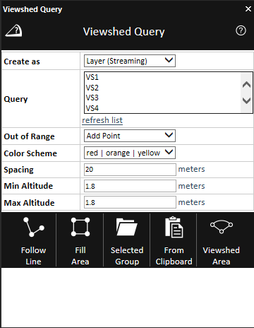
Viewshed Query
2. Select one of the Create as options:
|
Option |
Description |
|
Layer (Entire) |
Create a feature layer under the application’s AppData. |
|
Layer (Streaming) |
Create a streaming feature layer under the application’s AppData. |
3. Enter the following parameters:
|
Parameter |
Description |
|
Query |
The list displays all 3D viewsheds in the project. Only selected 3D viewsheds are taken into account when calculating the ratio between visible and invisible viewsheds. Click the required viewshed(s). Use CTRL-click or SHIFT-click to multi-select. Click Refresh list to update this list to the current project status. |
|
Out of Range |
Defines how to handle query points that are outside of the calculated areas of all selected 3D viewsheds. Select either: § Ignore Point - Do not add points outside of the range of any selected 3D viewshed. § Add Point - Add points outside of the range of any selected 3D viewshed. These query points are considered to have 0% visibility and color coded in red. |
|
Color Scheme |
Defines the color coding scheme of the output points. Select either red | green or red | orange | yellow | green. |
|
Spacing |
Determines the horizontal and vertical spacing (in meters) between query points in the area for which the viewshed query is being calculated. The spacing property also defines the scale of the output points. |
|
Min Altitude |
Defines the altitude above ground level of the closest point to the ground. |
|
Max Altitude |
Defines the maximum altitude above ground level. If the Max Altitude is higher than the Min Altitude, the 3D Viewshed Query tool generates a matrix of points according to the Spacing value. |
4. Select one of the following methods of designating the area for which the viewshed should be calculated:
§ Follow Line – Query points are created along the drawn line. In the 3D Window, left-click to place the line waypoints, and right-click to complete the line.
§ Fill Area – Query points are created inside the drawn polygon.
§ Selected Group – Query points are created at all points, along all lines, or inside all polygons, in the selected feature layer. Select the required layer from the Project Tree, and then click Selected Group.
§ From Clipboard - Query points are created at all clipboard objects.
§ Viewshed Area - Query points are created exactly in the area of the selected 3D viewsheds.