Text and image labels
You can do any of the following:
§ Create a graphic frame to surround a text or image label
Creating a new text label
To create a new text label:
1. On the Objects tab, in the Label group, click Text. The Enter Label Text dialog is displayed.
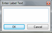
Enter Label Text Dialog
2. Type the text in the Enter Label Text dialog. You must enter a text and click OK before you can place the object in the 3D World.
3. The Text Label property sheet opens. Set the other parameters of the object. See "Text Label Property Sheet Parameters" in this chapter for more information.
4. If you want to position the label based on where the mouse is pointing in the 3D Window, on the top bar of the label’s property sheet, click Set Position Based on Mouse  . See "Moving an Object Based on Where the Mouse is Pointing in the 3D Window" in the "Working with Objects" chapter for more information.
5. If you want to position the label based on where the mouse is pointing in the 3D Window and snap it to another object, on the top bar of the label’s property sheet, click Snap Based on Snapping Options  . See "Moving an Object Based on Where the Mouse is Pointing in the 3D Window" and "Setting Snapping Options" in the "Working with Objects" chapter for more information.
6. If you want to position the label in the XY plane, on the top bar of the object’s property sheet, click XY Plane  . See "Moving an Object in the XY Plane" in the "Working with Objects" chapter for more information.
7. If you want to position the label in the Z plane, on the top bar of the object’s property sheet, click Z Plane  . See "Moving an Object in the Z Plane" in the "Working with Objects" chapter for more information.
8. Place the label in the 3D Window by clicking in the desired location.
9. Continue to edit the label’s parameters or close the property sheet to finish the operation.

Example of a Text Label with a Frame
Text label property sheet parameters
|
Object Parameter |
Activity |
|
Label |
|
|
Text |
Edit the text for the label. This is the text that appears in the 3D Window. |
|
Show Text |
§ Select Always to always display the label’s text. § Select On Hover to display the label’s text only when the mouse points to the label’s icon. Note: This field is enabled only if an image file was selected in the Image File field of the property sheet’s Image Options group. |
|
Text Color |
Sets the foreground color of the text Click the Edit button to open the Color dialog, or type the color code in the hexadecimal BBGGRR format (B = Blue channel 00-ff, G = Green channel 00-ff, R = Red channel 00-ff). |
|
Font Size |
Select the font size, in pixels, from the dropdown list. |
|
Font |
Select the font type from the dropdown list. |
|
Bold |
Select for Bold font style. |
|
Underline |
Select for Underline font style. |
|
Italic |
Select for Italic font style. |
|
Background Color |
Sets the background color of the label. Click the Edit button to open the Color dialog, or type the color code in hexadecimal BBGGRR format (B = Blue channel 00-ff, G = Green channel 00-ff, R = Red channel 00-ff). |
|
Background Opacity |
Enter the opacity value for the label’s background. The background covers the area of the label that is not covered by the text or by the image file. The opacity is defined as a percentage, where 100% is opaque and 0% is transparent. When the opacity is set to 0%, the characters are surrounded by a solid background color outline to highlight the text. |
|
Scale |
Scale factor applied to the label. The maximum character height is the Text Size times the Scale value. This property is only enabled when Scaling Mode is set to Fixed Real-World-Size. |
|
Scaling Mode (previously "Limit Growth") |
Select either of the following: § Fixed Pixel Size – Keeps the label size in pixels constant, regardless of zoom. § Fixed Real-World Size – Keeps the label size constant in real world units, so it appears smaller when you zoom out and larger when you zoom in. |
|
Frame File |
Add a graphic frame to the label. Click Edit to open the image selection dialog and choose from available icons in the Data Library. To use an image from your computer, click Browse File System and navigate to the desired file. Supported formats include BMP and GIF. See "Label’s Frame File Format" section in this chapter for further information on how to create frame files. |
|
Frame Index |
Select the index of the frame in the frame file. This field is only available if a frame file is selected. See "Label’s Frame File Format" for further information on how to create frame files. |
|
Lock Mode |
Set which text label position parameters are adjusted automatically to face the camera and which are locked to the Position group field values (See Position group below). § Decal: The text label position and reading direction are adjusted automatically to face the camera. § Axis: All text label position parameters are locked to the Position group field values. § Axis Text Up: The text label reading direction is adjusted automatically to face the camera whereas the text label position is set to the Position group field values (see below). § Axis (Auto Pitch): The text label pitch angle is adjusted automatically to face the camera whereas the other position parameters are set to the Position group field values. § Axis (Auto Pitch Text Up): The text label reading direction and pitch angle are adjusted automatically to face the camera. The other position parameters are set to the Position group field values § Axis (Auto Yaw): The text label yaw angle is adjusted automatically to face the camera, while the other position parameters are set to the Position group field values. |
|
Image |
|
|
Image File |
Add an image as a background to the text. Click Edit to open the image selection dialog and choose from available icons in the Data Library. To use an image from your computer, click Browse File System and navigate to the desired file. Supported formats include BMP, JPEG, GIF, PNG, and ICO. To use a label that contains only an image (without text), select the Image Label option on the Objects tab. |
|
Image Color |
Sets the color of the image. Click the Edit button to open the Color dialog, or type the color code in hexadecimal BBGGRR format (B = Blue channel 00-ff, G = Green channel 00-ff, R = Red channel 00-ff). |
|
Image Opacity |
Enter the opacity value for the image. The opacity is defined as a percentage, where 100% is opaque and 0% is transparent. |
|
Image Size |
Enter a maximum size in pixels for the image. If no value is provided, the image's original pixel size is used. |
|
Determines how the label's image blends with the background terrain or model layer: § On – Adds the image color to the background, e.g., if the terrain is green (RGB: 0, 255, 0), and a red label is drawn on it (RGB: 255, 0, 0), its RGB value is added to the background, to produce a yellow blend (RGB: 255, 255, 0). § Off – Uses normal blending based on the opacity set for the image. |
|
|
Position |
|
|
Altitude Method |
Sets the altitude method to be used by the label: § Select Relative to Terrain to place the label’s pivot point at a specified altitude above the ground. § Select Absolute to place the label’s pivot point at a specified altitude above the terrain database vertical datum base ellipsoid. § Select Relative to 3DML to place the label's pivot point at a specified altitude above the 3DML layer. |
|
Altitude |
Enter the altitude, as defined in Altitude Method, for the text label’s pivot point. |
|
X |
Enter the X-coordinate for the text label’s pivot point. |
|
Y |
Enter the Y-coordinate for the text label’s pivot point. |
|
MGRS |
The coordinates of the text label’s pivot point in Military Grid Reference System (MGRS) coordinates. This field is only available if Show MGRS Coordinates was selected in the Options dialog. See "View" in the "Using TerraExplorer Options" chapter for more information. |
|
Yaw |
Determines the direction angle of the text label along the vertical axis relative to north. |
|
Pitch |
Determines the tilt angle of the text label along its lateral axis relative to the horizon. |
|
Roll |
Determines the roll angle of the text label along its longitudinal (front-to-back) axis. |
|
Pivot Alignment |
Determines the alignment of the label relative to its pivot point. Select Top, Left; Top, Center; Top, Right; Center, Left; Center, Center; Center, Right; Bottom, Left; Bottom, Center; Bottom, Right. |
|
Text & Image Alignment |
|
|
Multiline Justification |
If there is more than one line of text, this option determines the justification of the text. Select Left Justify, Center Justify or Right Justify. |
|
Text Relative to Image |
Select Text on Image to display the text on the background image. Select Text Around Image to display the text next to the background image. |
|
Text Alignment |
Horizontal and Vertical justification of the text with respect to the background image. Select Top, Left; Top, Center; Top, Right; Center, Left; Center, Center; Center, Right; Bottom, Left; Bottom, Center; Bottom, Right. |
|
Visibility |
|
|
Min. Visibility Height |
Determines the minimum viewing height at which the label is visible. The label disappears when flying lower than the "Min Viewing Height". |
|
Max. Visibility Distance |
Sets the distance from the camera at which the label disappears. |
|
Max. Show-Through Dist. |
Sets the maximum distance of label's pivot from camera, in meters, beyond which it will not show through terrain, mesh layers, or objects that are hiding it. Set to -1 to enable show-through at any distance when editing the label. When an object is showing through terrain, mesh or objects, it can be selected, edited, and snapped to other objects. |
|
Viewing Distance |
Determines the viewing distance of the camera from the label. This distance is used as a stop mark for any "Fly-to" or "View Object" operation. It is also used when selecting to edit the object from the Project Tree. When this value is set to the default of -1, TerraExplorer calculates and sets the ideal viewing distance for the label based on its size. |
|
Activation Action |
Select the action to perform when selecting the object from the Project Tree. See "Navigating to Objects" in the "Navigating in the 3D World" chapter for information |
|
Visibility |
This property is only displayed for point features in a feature layer. Sets the visibility of features based on their attribute values. Type a search expression comprised of one or more conditions, or click the Field by Attribute button |
|
General |
|
|
Tree Name |
Type the description or name of the label. This text appears in the Project Tree as the name of the object. |
|
Message |
The message associated with the text label. The number displayed is the number of the message. To create a new message, or update an existing message, open the Create Message dialog by clicking in this field and selecting Edit. See "Using the Create Message Dialog" in the "Working with Objects" chapter for more information. |
|
Tooltip |
Type a tooltip text to appear when the mouse cursor is placed over the text label in the 3D Window. |
|
Line to Ground |
Adds a line from the label’s pivot point either to the ground or to a custom length towards the ground. Note: A line to ground is displayed while the label is being edited (i.e., as long as its property sheet is open), regardless of this property value. This property only determines whether a line to ground will continue to display even after the label’s property sheet is closed. |
|
Line Length |
Determines the length of the line to the ground. This property is available only when the "Line to Ground" parameter is set to "Custom Length". |
|
Line Color |
Sets the color of the label’s line to ground. Click the Edit button to open the Color dialog, or type the color code in hexadecimal BBGGRR format (B = Blue channel 00-ff, G = Green channel 00-ff, R = Red channel 00-ff). This property is available only when the "Line to Ground" option is set to "To Ground" or "Custom Length". |
|
Timespan |
|
|
Start Time |
Click Edit and enter the date and time the label should first become visible. |
|
End Time |
Click Edit and enter the date and time the label should stop being visible. |

Creating a new image label
To create a new image label:
1. On the Objects tab, in the Label group, click Image. The Browse for Image dialog is displayed.
2. Select one of the available icons in the Data Library. To use an image from your computer, click Browse File System and navigate to the desired file. Supported formats include BMP, JPEG, GIF, PNG, and ICO.
3. Set the object’s other parameters. See "Image Label Property Sheet Parameters" in this chapter for more information.
4. Place the label in the 3D World by clicking in the desired location.
5. Continue to edit the label’s parameters or close the property sheet to finish the operation.
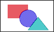
Example of an Image Label
Image label property sheet parameters
|
Object Parameter |
Activity |
|
Image |
|
|
Image File |
Click Edit to open the image selection dialog and choose from available icons in the Data Library. To use an image from your computer, click Browse File System and navigate to the desired file. Supported formats include BMP, JPEG, GIF, PNG, and ICO. |
|
Scale |
Scale factor to apply to the image. This property is only enabled when Scaling Mode is set to Fixed Real-World-Size. |
|
Scaling Mode (previously "Limit Growth") |
Select either of the following: § Fixed Pixel Size – Keeps the label size in pixels constant, regardless of zoom. § Fixed Real-World Size – Keeps the label size constant in real world units, so it appears smaller when you zoom out and larger when you zoom in. |
|
Image Color |
Sets the color of the image. Click the Edit button to open the Color dialog, or type the color code in hexadecimal BBGGRR format (B = Blue channel 00-ff, G = Green channel 00-ff, R = Red channel 00-ff). |
|
Image Opacity |
Enter the opacity value for the image. The opacity is defined as a percentage, where 100% is opaque and 0% is transparent. |
|
Image Size |
Image size. When Scaling Mode is set to Fixed Pixel Size, the size is defined in pixels. When set to Fixed Real-World Size, the size is defined in meters. If no value is provided, the image's original size is used. |
|
Blend Mode |
Determines how the label's image blends with the background terrain or model layer: § On - Adds the image color to the background, e.g., if the terrain is green (RGB: 0, 255, 0), and a red label is drawn on it (RGB: 255, 0, 0), its RGB value is added to the background, to produce a yellow blend (RGB: 255, 255, 0). § Off – Uses normal blending based on the opacity set for the image. . |
|
Frame File |
Add a graphic frame to the label. Click Edit to open the image selection dialog and choose from available icons in the Data Library. To use an image from your computer, click Browse File System and navigate to the desired file. Supported formats include BMP and GIF. See "Label’s Frame File Format" section in this chapter for further information on how to create frame files. |
|
Frame Index |
Select the index of the frame in the Frame File. This field is only available if a Frame File is selected. See "Label’s Frame File Format" for further information on how to create frame files. |
|
Lock Mode |
Set which image label position parameters are adjusted automatically to face the camera and which are locked to the Position group fields values (See Position group below). § Decal: The image label position and reading direction are adjusted automatically to face the camera. § Axis: All image label position parameters are locked to the Position group field values. § Axis Text Up: The image label reading direction is adjusted automatically to face the camera whereas the image label position is set to the Position group field values (see below). § Axis (Auto Pitch): The image label Pitch angle is adjusted automatically to face the camera whereas the other position parameters are set to the Position group field values. § Axis (Auto Pitch Text Up): The image label reading direction and Pitch angle are adjusted automatically to face the camera. The other position parameters are set to the Position group field values. § Axis (Auto Yaw): The image label yaw angle is adjusted automatically to face the camera, while the other position parameters are set to the Position group field values. |
|
Position |
|
|
Altitude Method |
Sets the altitude method to be used by the image label: § Select Relative to Terrain to place the image label’s pivot point at a specified altitude above the ground. § Select Absolute to place the image label’s pivot point at a specified altitude above the terrain database vertical datum base ellipsoid. § Select Relative to 3DML to place the image label's pivot point at a specified altitude above the 3DML layer. |
|
Altitude |
Enter the altitude, as defined in Altitude Method, for the image label’s pivot point. |
|
X |
Enter the X coordinate for the image label’s pivot point. |
|
Y |
Enter the Y coordinate for the image label’s pivot point. |
|
MGRS |
The coordinates of the label’s pivot point in Military Grid Reference System (MGRS) coordinates. This field is only available if Show MGRS Coordinates was selected in the Options dialog. See "View" in the "Using TerraExplorer Options" chapter for more information. |
|
Yaw |
Determines the direction angle of the image label along the vertical axis relative to north. |
|
Pitch |
Determines the tilt angle of the image label along its lateral axis relative to the horizon. |
|
Roll |
Determines the roll angle of the image label along its longitudinal (front-to-back) axis. |
|
Pivot Alignment |
Determines the alignment of the label relative to its pivot point. Select Top, Left; Top, Center; Top, Right; Center, Left; Center, Center; Center, Right; Bottom, Left; Bottom, Center; Bottom, Right. |
|
Visibility |
|
|
Min. Visibility Height |
Determines the minimum viewing height at which the label is visible. The label disappears when flying lower than the "Min Viewing Height". |
|
Max. Visibility Distance |
Sets the distance from the camera at which the label disappears. |
|
Max. Show-Through Dist. |
Sets the maximum distance of label's pivot from camera, in meters, beyond which it will not show through terrain, mesh layers, or objects that are hiding it. Set to -1 to enable show-through at any distance when editing the label. When an object is showing through terrain, mesh or objects, it can be selected, edited, and snapped to other objects. |
|
Viewing Distance |
Determines the viewing distance of the camera from the label. This distance is used as a stop mark for any "Fly-to" or "View Object" operation. It is also used when selecting to edit the object from the Project Tree. When this value is set to the default of -1, TerraExplorer calculates and sets the ideal viewing distance for the label based on its size. |
|
Activation Action |
Select the action to perform when selecting the object from the Project Tree. See "Navigating to Objects" in the "Navigating in the 3D World" chapter for information |
|
General |
|
|
Tree Name |
Type the description or name of the label. This text appears in the Project Tree as the name of the object. |
|
Message |
The message associated with the label. The number displayed is the number of the message. To create a new message, or update an existing message, open the Create Message dialog by clicking in this field and selecting Edit. See "Using the Create Message Dialog" in the "Working with Objects" chapter for more information. |
|
Tooltip |
Type a tooltip text to appear when the mouse cursor is placed over the label in the 3D Window. |
|
Line to Ground |
Adds a line from the label’s pivot point either to the ground or to a custom length towards the ground. Note: A line to ground is displayed while the label is being edited (i.e., as long as its property sheet is open), regardless of this property value. This property only determines whether a line to ground will continue to display even after the label’s property sheet is closed. |
|
Line Length |
Determines the length of the line to the ground. This property is available only when the "Line to Ground" parameter is set to "Custom Length". |
|
Line Color |
Sets the color of the label’s line to ground. Click the Edit button to open the Color dialog, or type the color code in hexadecimal BBGGRR format (B = Blue channel 00-ff, G = Green channel 00-ff, R = Red channel 00-ff). This property is available only when the "Line to Ground" option is set to "To Ground" or "Custom Length". |
|
Timespan |
|
|
Start Time |
Click Edit and select the date and time when the label should first become visible. |
|
End Time |
Click Edit and select the date and time when the label should stop being visible. |
Label frame file format
Text and Image labels can include a graphic frame surrounding the text or the image. The file that contains the frame patterns can be either a BMP or a GIF file. A single file can hold several frame patterns.
To select a frame for a label:
§ Choose the frame file name and the index of the frame within the file. You can use one of the pre-prepared frame files included in the Data Library, or you can create a custom-made frame file.
Preparing a frame pattern
1. Draw a small pattern of a frame. You can draw it in any size and number of colors. The actual size of the frame is adjusted for each label.

Frame
2. Mark the corners of the frame by drawing 3 pixels per corner, as shown below. Use the same color for marking all the pixels.

Marked Frame
Note: When a pattern is used to create a frame for a label, the size of the corners is not changed. Rather, the edges are either stretched or repeated to fit the label.
3. By default, the edge is repeated to fit the label. If you want the edge to be stretched, draw another pixel attached to the edge.
§ For the top and bottom edges, the pixel should be attached to the left corners.
§ For the left and right edges, it should be attached to the top corners.
§ Each edge, within one pattern, can have a different width and can be either stretched or repeated.

Example of frame with Stretched Top and Bottom Edges

Example of Frame with Stretched Left and Right Edges
4. To combine several frames to one file, align all the frame images (with their marking-pixels) to the top of the image file, and align the first (left) pattern (with its marking-pixels) to the left side of the image file.
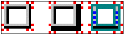
Example of an Image File Containing Three Frame Patterns
Note: There must be a space of at least one pixel between any two patterns. The space can be of more than one pixel.