Modifying 3D Layers
3D layers can be modified to correct positioning and geometric imperfections. TerraExplorer also provides tools for slicing and classifying 3D layers, enabling clearer visualization, inspection, and data querying.
§ Raise or lower the 3DML surface
§ Correct inaccuracies in the scale, rotation, and positioning of 3D mesh layers
Modifying a 3D mesh layer's elevation
Elevation values in an area of a 3DML are modified using a modify mesh object. The surface of the 3DML is raised or lowered according to the elevation values of the modify mesh polygon's points. Different elevation behaviors allow replacing, cropping above or cropping below the original values of the terrain. The interior of the polygon can be flat or irregular in shape.
To modify a 3D mesh layer:
1. In the Project Tree, select the required layer.
2. On the 3D Layer tab, in the General group, click Modify Mesh Layer. The Modify Terrain property sheet is displayed.
3. In the 3D Window, left-click to place the modify mesh polygon’s waypoints, and right-click to complete.
4. In the property sheet, set the modify mesh polygon’s properties. See "Modifying the Terrain" in the "Objects and Labels" chapter for more information.
Scaling and rotating 3D mesh layers
Inaccuracies in 3D mesh layers' scale, rotation and positioning can be corrected using the Scale and Rotate tool and saved in the layer's file. These inaccuracies generally stem from inaccurate positioning hardware.
Note: Scale, rotation, and positioning values can also be modified in the mesh layer’s property sheet. See "Setting and Editing 3D Layer Properties" in this chapter for more information. When properties are only modified in the property sheet, the mesh layer is only changed in the specific project's Fly file. Changes are saved to the mesh layer itself only if they are made using the Scale and Rotate tool.
To scale, rotate, and reposition a 3D mesh layer:
1. In the Project Tree, select the required layer.
2. On the 3D Layer tab, in the Mesh Layer group, click Scale and Rotate. The Scale and Rotate dialog is displayed.
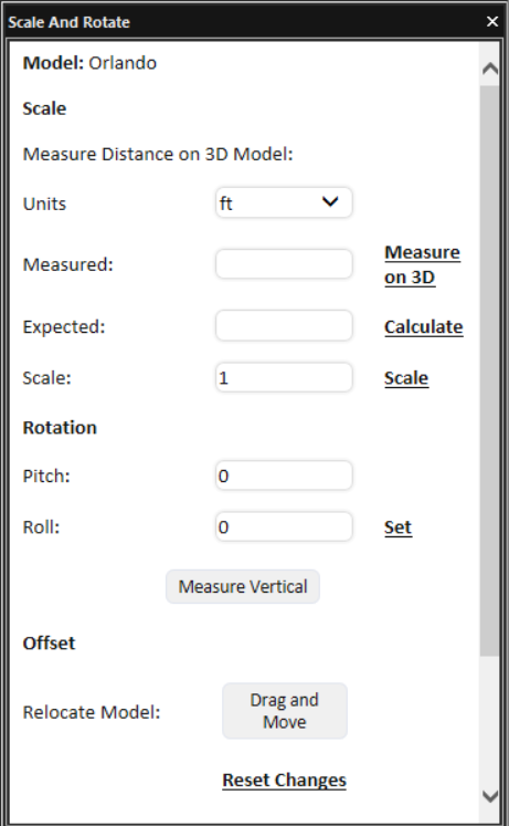
Scale and Rotate Dialog
3. Set the required scale: If you know the required scale value, enter it in the Scale field and click Scale. Otherwise, you can set the scale by measuring a specific, generally, easily distinguishable section of the model and calculating the ratio of the expected measurement (based on the real world measurement) to the actual measurement. Do the following:
a. The Units value is automatically populated with the units set for Altitude and Distance in the Options dialog See "View" in "Using TerraExplorer Options" for more information. If you want to use different units, select the required Units.
b. Click Measure on 3D.
c. In the 3D Window, mark the two endpoints of the section of the model that you want to measure, and right-click to set the distance value in the Measured field.
d. In the Expected field, enter the actual, real world measurement of this section of the model.
e. Click Calculate to calculate the scale factor and resize the model. The scale factor is calculated based on the ratio between the Expected and Measured values and entered in the Scale field.
4. Set the required rotation: The Pitch and Roll values are populated automatically based on the model’s property sheet. If you know the required Rotation values, enter them. Alternatively, if you have two points on the model that you know should be vertically aligned, e.g., the base and top of a flag pole, you can mark these points, and TerraExplorer can use this information to adjust the pitch and roll so that these points will actually be vertically aligned. Do the following:
a. Click Measure Vertical.
b. On the model, click a point on the bottom and then click a point towards the top that should be directly above the first point. The model’s new pitch and roll are calculated and entered in their respective fields.
c. Click Set to set the model’s rotation according to the new values.
5. Change the model’s position: In the Offset section, do the following:
a. Click Drag and Move. The model’s property sheet is displayed.
b. In the property sheet, modify the layer’s properties or click Move in XY Plane  or Move in Z Plane
  to drag the model to the required position in the 3D Window. See "Setting and Editing 3D Layer Properties" in this chapter for more information.
6. If you want to reset the dimensions, rotation, or position of the model to the original value, click Reset changes.
7. Select one of the Output Format options:
§ 3D Mesh
§ 3D Mesh and LAS
§ 3D Mesh and LAZ
8. If you selected an output format option that includes LAS/LAZ point cloud, set the Point Cloud Resolution in meters/pixel.
9. Click Convert Model. The tool opens the SLMesh Converter command line tool to generate a new 3DML file with the corrected scale, rotation and location. The new model is created in the same folder as the original model.
10. To view the new model, load it into the project.
Marking 3D and ortho layers for retouching in PhotoMesh
Manual retouch enables you to correct 3D layer imperfections such as bumps, uneven surfaces, or floating artifacts, as well as to define water bodies. Retouch is performed through a shared retouch layer that is exchanged between PhotoMesh and TerraExplorer. Currently, retouch is supported only for mesh layers. Gaussian Splatting layers are not supported.
An SQLite retouch layer is first exported from PhotoMesh and loaded into TerraExplorer, where additional retouch markings are created by drawing or importing polygons and polylines. These markings are stored directly in the retouch layer. Once editing is complete, the same SQLite retouch layer is reimported into PhotoMesh and applied during project rebuild to constrain the reconstruction process.
The retouch layer contains polygonal features with attributes that define the required action for each marked area, such as clean, flatten, or retexture. During rebuild, PhotoMesh updates the 3D layer geometry accordingly and retextures the affected areas using the project’s photos, a selected color, or with a specified file based texture such as water or grass.
The visual reference used to define retouch areas can be either of the following:
§ Mesh mode. A 3D model, either the reconstruction tile’s textured model or the final 3D layer
§ Ortho mode. Orthophoto output
To mark a 3D or ortho layer for retouch:
1. Load the target output. The outputs produced in PhotoMesh are found in the build’s outputBuild folder, each output type in its own folder. See "Accessing the Build Outputs" in the PhotoMesh User Guide for more information.
§ For Mesh mode, load the 3D layer on which you want to mark the retouches.
§ For Orthophoto mode, load the orthophoto output.
Note: If the loaded 3D layer's vertical coordinate system is different from the terrain’s, the elevation values must be reprojected. See "Setting and Editing 3D Layer Properties" in the "3D Layers" chapter for more information.
2. Load an SQLite retouch layer (retouch.sqlite) that was exported from PhotoMesh. See the PhotoMesh User Guide for information. See "Loading Feature Layers" in the "Feature Layers" chapter for more information on loading the retouch layer.
3. In the Project Tree, select the loaded SQLite retouch layer, and then on the Tools tab, in the PhotoMesh group, click Manual Retouch. The Manual Retouch dialog is displayed.
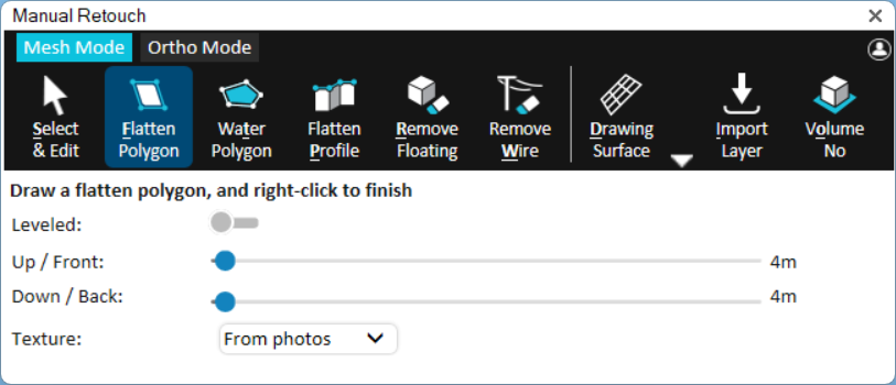
Manual Retouch
4. If this is the first time you are opening the retouch layer in this TerraExplorer project, the Enter User Name dialog is displayed so you can tag your edits with your name. To open this dialog at a different time, click the user name link  in the Manual Retouch dialog. The user name entered here is saved in the layer’s username attribute. When multiple users work on the same retouch layer, this attribute enables you to identify the particular user that worked on each retouch polygon.
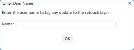
Enter User Name Dialog
5. Select a mode and perform your retouch operations:
§ Mesh Mode – Mark your edits on a 3D layer output (the reconstruction tile’s 3D textured model or the final 3D mesh or Gaussian Splatting model). See "Working in Mesh Mode" for more information.
§ Ortho Mode - – Mark your edits on the orthophoto output. See "Working in Orthophoto Mode" for more information.
6. All changes to the retouch layer are automatically saved, so no export of the retouch layer is required. When finished, import the SQLite retouch layer back into PhotoMesh.
Note: If the SQLite retouch layer that was exported from PhotoMesh is open in PhotoMesh when marking the retouch operations in TerraExplorer, changes may not be saved automatically to the layer. Changes can be manually saved from the Feature Layer tab > Save Layer.
Working in mesh mode
Mesh mode provides a range of retouch operations for flattening, filling, or cleaning up any 3D layer imperfection. You can either import a polyline or polygon feature layer in shp, sqlite, or gpkg format with retouch polylines/polygons, or create the retouch polylines/polygons directly in TerraExplorer.
When setting a buffer for retouch polygons/polylines, by default, polygons with an elevation angle below 20° are extruded vertically. For clockwise-drawn polygon/polyline, the front side faces the viewer.
The following retouch-related actions are available in Mesh mode:
§ Import a Retouch or Water Polygon/Polyline
Selecting a retouch operation
The following operations can be performed in mesh mode:
§ Flatten polygon – Replace all elements inside the polygon's volume with a flat surface based on the polygon footprint. This is commonly used for filling holes and flattening walls. The area of the 2D polygon can be textured with any of the following:
§ From photos – Fill the polygon area using photos from the area.
§ Remove moving cars – Fill the polygon area using only photos from the area that don’t include moving cars. This option offers a solution to undesirable reconstruction effects that can occur when capturing an area with moving cars (e.g., a car that is partially sunk in the road), since only some of the captured photos included the cars, while others did not. It is recommended to individually retouch each car you want to remove by applying a unique polygon to it.
§ Single color – Fill the polygon area using a single color.
§ Texture pattern – Fill the polygon area with a water or grass texture.
§ Flatten profile – Create multiple flatten polygons by defining a profile line (usually on a roof top) and the base elevation. A flatten polygon is created for each segment of the profile line (from the line to the base elevation). This method is useful for creating retouch polygons in hard to access places, e.g., between buildings.
§ Remove floating – Remove all elements inside a defined volume. This option is generally used to remove floating elements that aren’t connected to the ground.
§ Remove wire – Remove thin elements such as power lines by drawing a polyline that marks the wire to be removed. A separate floating polygon is created for each segment of the polyline.
§ Water polygon - Detects and flattens water surfaces by analyzing texture colors within the drawn polygon.
To perform a retouch operation in Mesh mode, do the following:
1. To create a surface on which to draw your retouch polygon or polyline, e.g., for a model that is not flat or missing corners, click the arrow next to Drawing Surface (Shortcut key: d) and select one of the options. See "Using Drawing Surfaces" in the "Working with Objects" chapter for information.
2. To create a Flatten polygon (Shortcut key: f):
a. Switch Leveled on to set the altitude of all polygon points to that of the first point.
b. Set a buffer for the retouch polygon upwards or frontwards and downwards or backwards in the direction of the polygon’s normal by sliding the Up/Front buffer and Down/Back buffer sliders.
c. Select one of the fill options: From photos, Remove moving cars, Single color, or Texture pattern.
d. For Single color fill, select the color to use. For Texture pattern fill, select a Texture pattern, and enter a value for the texture tile size.
e. Draw a polygon around the area for flattening. Right-click to complete.
3. To create a Flatten profile (Shortcut key: p):
a. Set a buffer for the retouch polygon upwards or frontwards and downwards or backwards in the direction of the polygon’s normal, by sliding the Up/Front buffer and Down/Back buffer sliders.
b. Draw the profile line, and then right-click to complete. Then click on the model to define the model's base elevation. A flatten polygon is created for each segment of the profile line, extending from the line to the base elevation.
4. To remove floating (Shortcut key: r):
a. Click any point on the floating artifact. PhotoMesh automatically creates a polygon that includes the selected point.
b. Set a buffer for the retouch polygon upwards or frontwards and downwards or backwards in the direction of the polygon’s normal, by sliding the Up/Front buffer and Down/Back buffer sliders.
5. To remove a wire (Shortcut key: w):
a. Set a buffer for the retouch polyline upwards or frontwards and downwards or backwards in the direction of the polyline’s normal, by sliding the Front buffer and Back buffer sliders.
b. Set the Wire Width.
c. Draw a polyline along the wire to remove, and then right-click to complete. A retouch polygon is created for each polyline segment, with the width based on the specified Wire Width value.
6. To create a Water polygon:
a. Select a Water Type.
§ Smart Water – Detects and flattens water surfaces by analyzing texture colors within the drawn polygon. Even a rough outline is often sufficient. Smart Water also identifies and preserves above-water features such as boats and bridges. To apply this process, PhotoMesh downgrades the affected tiles back to the Point Cloud phase. The polygon must be drawn at an elevation as close as possible to the actual water surface. If the elevation is inaccurate, too high or too low, the water detection may fail or produce incorrect results.
§ Flat Water – Begins with the Smart Water detection process but then overrides the entire polygon area, flattening it completely, regardless of whether water was detected. This ensures a uniform, artifact-free surface, even in areas where water detection may have failed.
b. Set the Leveled switch:
§ On (Leveled) – A constant water level (i.e., altitude) is set for all points in the water body polygon, to create level water bodies such as seas, lakes, ponds, and pools. This is especially useful for creating a level water body on top of a non-flat terrain or mesh, or for creating a flat water body based on an imported polygon with variable altitude values.
§ Off (Sloped) – PhotoMesh segments the water body polygon into multiple flat reconstruction tiles, each of which has a different elevation value based on the average elevation within the specific tile. This option should be selected to create an elevation gradient for water bodies such as rivers, with non-uniform water levels.
c. If you selected Flat Water for the Water Type, set a buffer for the retouch polygon upwards or frontwards and downwards or backwards in the direction of the polygon’s normal by sliding the Up/Front buffer and Down/Back buffer sliders.
d. With the cursor in the 3D Window, click to add the first point of the polygon. Click again to add additional points of the polygon until you have marked the entire shape. You must place at least three points to define the polygon. When creating a water body polygon, the lines of the polygon should not overlap each other.
e. Right-click to finish the polygon.
7. To select how to display all manual retouch polygons, click the Volume icon (Shortcut key: o):
§ Volume Colorize – Mark the area for retouching by colorizing all parts of the mesh contained within the extruded polygon.
§ Volume Polygon – Mark the area for retouching by displaying 3D polygons based on the extruded polygon.
§ Volume No – Mark the area for retouching only with a 2D polygon.
Editing a retouch polygon/polyline
To edit a retouch polygon/polyline after it is drawn:
1. In the Manual Retouch dialog, click Select and Edit (Shortcut key: s).
2. Select the retouch object. A mini editing toolbar is displayed along with the properties relevant to the selected retouch object. See "Editing Objects in the 3D Window" in the "Working with Objects" chapter and "Performing a Retouch Operation" in this chapter for information.
Note: When editing a Flatten Profile or Remove Wire retouch object, only the selected polygon segment is modified.
Working in ortho mode
The following retouch operations are available in Ortho mode:
§ Clean Cars – Remove all elements inside a defined area, and texture the drawn polygon area using only photos from the area that don’t include moving cars. This option offers a solution to undesirable effects in the reconstruction (e.g., a car that is partially sunk in the road) that can occur when capturing an area with moving cars, since only some of the captured photos included the cars, while others did not. It is recommended to individually retouch each car you want to remove by applying a unique polygon to it.
§ Clean Edges – Remove artifacts along the edges of a model.
§ Import Layer – Import a polyline or polygon feature layer with retouch polylines/polygons for cleaning edges or cars. The following layer formats are supported: .shp, sqlite, and gpkg.
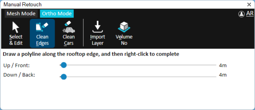
Manual Retouch – Ortho Mode
To perform a retouch operation in Ortho mode:
1. Select one of the retouch operations in the Manual Retouch dialog, and then do the following:
§ Clean Cars (Shortcut key: c)
i. Draw a polygon around the area that you want to clean.
ii. Right-click to complete. The buffers are automatically set to 10 meters above/below the surface.
§ Clean Edges (Shortcut key: e)
i. Set a buffer for the retouch polygon upwards or frontwards and downwards or backwards in the direction of the polygon’s normal by sliding the Up/Front buffer and Down/Back buffer sliders. If a polygon’s elevation angle to the ground is less than 20 degrees, the polygon is extruded vertically. If the polygon points were created in a clockwise orientation, then the front is the side facing the user.
ii. Draw a polyline along the edge you want to clean. Right-click to complete. A polygon is generated with the base line on the ortho surface and the bottom line, one meter below the surface. All artifacts with normal vertical to the polygon are cleaned.
§ Import Layer (Shortcut key: i)
i. Click Import Layer,and then Browse, and browse to the required layer. See "Importing polygon and polyline feature layers for retouching" in this chapter for more information.
2. To select how to display the drawn polygon, click the Volume icon (Shortcut key: o):
§ Volume Colorize – Mark the area for retouching by colorizing all areas contained within the extruded polygon.
§ Volume Polygon – Mark the area for retouching by displaying 3D polygons based on the extruded polygon.
§ Volume No – Mark the area for retouching only with a 2D polygon.
3. To select the polygon for editing after it is drawn, click Select and Edit (Shortcut key: s), and then select the retouch object for editing. Use the mini toolbar to edit the polygon. See "Editing a retouch polygon/polyline" in this chapter for information.
Importing polygon and polyline feature layers for retouching
Polygon and polyline layers created in external software can be imported in both Mesh and Orthophoto modes and automatically converted to retouch elements. Supported formats include: .shp, sqlite, and gpkg. The imported layer must include Z-values. The imported polylines are automatically converted to “flatten profiles” with a default profile height of one meter.
To import a layer with polygons/polylines for retouching:
1. In the Manual Retouch dialog, click Import Layer, and then Browse.
2. Browse to the required layer and click Import. The following layer formats are supported: .shp, sqlite, and gpkg. Then click Next.
3. Set the imported layer’s coordinate system. Then click Next.
4. In Ortho mode, switch on Intersect with project to import only polygons or polylines that intersect with the project, and click Import.
5. In Mesh mode, if a polygon layer was selected, do the following:
a. Select the Retouch Operation to perform using the imported polygons. See "Performing a retouch operation" in this chapter for more information.
Note: In Ortho mode and for polylines in both modes, the Retouch Operation is always Convert to profile, which converts the imported features to “flatten profiles” with a default vertical distance of one meter.
b. Select the elevation behavior of the imported polygons:
§ Leveled – A constant level (i.e., altitude) is set for all points in the polygon.
§ Non-Leveled (Sloped) – PhotoMesh segments the polygon into multiple flat reconstruction tiles, each of which has a different elevation value based on the average elevation within the specific tile.
c. Switch on Intersect with project to import only polygons or polylines inside the project (AT) area.
d. Click Import. The imported polygons/polylines are added to your retouch layer.
Slicing a 3D layer
The Slice Model tool slices the selected 3D layer to expose the interior of buildings or obscured sections of the 3D View. The tool is applied to the entire 3D layer and progressively removes portions of the layer in the selected direction using a slider.
To use the Slice Model tool:
1. In the Project Tree, select the required layer.
2. On the 3D Layer tab, in the General group, click the arrow next to Display Tools, and select Slice Model. The Slice Model controls are displayed.
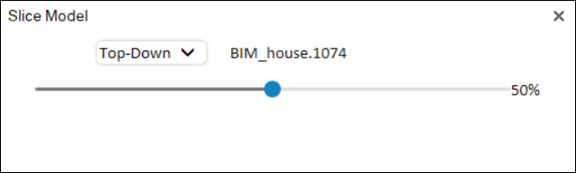
Slice Model Dialog
3. Select a slicing mode:
§ Top-Down – Removes mesh from the top of the layer downward.
§ Bottom-Up – Removes mesh from the bottom of the layer upward.
§ Front Cut – Removes mesh from the front of the layer toward the back.
4. Adjust the slice position using the slider. Slide all the way to the left to display the entire mesh, and all the way to the right to fully slice it in the selected direction. As the slider moves between these extremes, mesh is progressively removed to reveal the interior of the model.
Classifying a 3D layer
3D layers are classified using polygons that enable you to visually distinguish different areas of the mesh layer, access the attribute data of the classification features and perform spatial and attribute queries on the feature layer that is classifying the 3D layer. The classification is dynamic, reflecting any changes to the polygon features, and requires no pre-processing. See "Classifying Layers and Objects Using Feature Layers" in the "Feature Layers" chapter for information.
Skyline continues to also provide legacy support for pre-processed, classified mesh layers created in older versions of TerraExplorer Pro that have associated feature layers. These mesh layers support many of the editing, analysis, and querying capabilities available for standard feature layers, including spatial and attribute queries. See "Working with 3DML's Feature Layers" in this chapter for information.