Sharing and Exporting 3D Layers
3D layers can be uploaded to SkylineGlobe Server or exported to other formats for use in external applications.
Uploading 3D layers to SkylineGlobe Server
You can upload 3D layers in 3DML or o3DML format to SkylineGlobe Server.
To upload a layer:
§ In the Project Tree, right-click the required layer, and select Upload to SkylineGlobe from the shortcut menu. See "Uploading Layers to SkylineGlobe Server" in the "Working with SkylineGlobe Server" chapter for information.
Exporting 3D layers to models, point cloud, and ATAK
3D layers (3DML/o3DML) and 3D Tiles generated by PhotoMesh can be exported to individual 3D models, LAS point cloud layers, or ATAK (for use with the ATAK mobile application). Other mesh formats (OSGB, DAE – LODTreeExport) that were generated by PhotoMesh can be imported into TerraExplorer, converted to 3DML, and then exported to these formats.
You can define the export area using any of the following methods:
§ Select a feature layer
§ Use polygons from the clipboard
§ Draw a polygon
The number of files created for each polygon depends on the grid size setting that you select. You have the option to split the extracted area into either 3D boxes or a 2D grid.
In addition to the export methods supported from TerraExplorer user interface, additional export options can be performed from the SLMeshConverter command line tool. See "Importing and Exporting Using the Command Line" in this chapter for information.
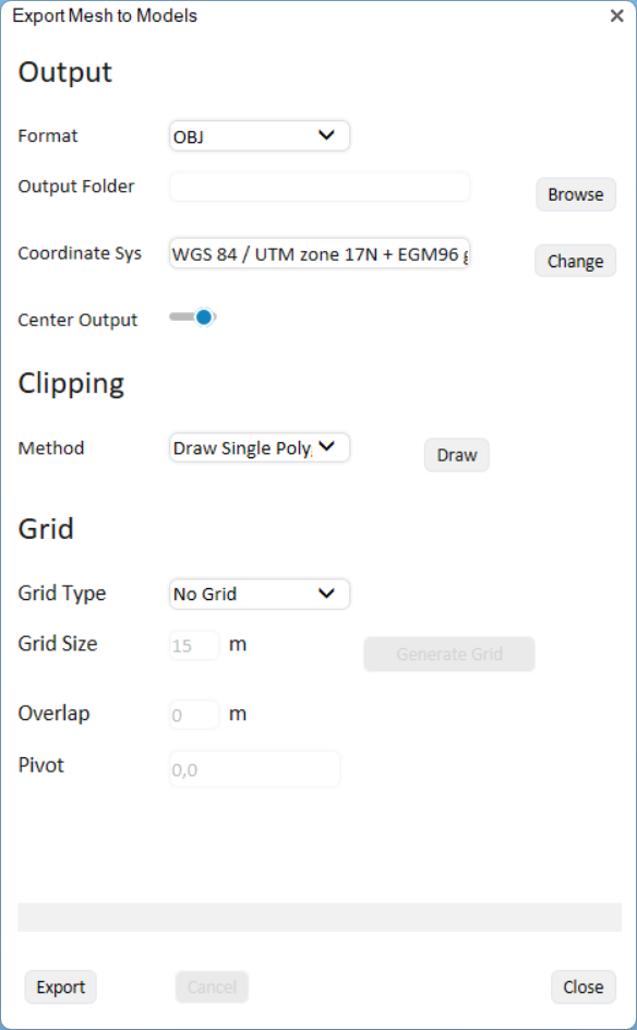
Export Mesh to Models
To export a mesh layer to individual models / LAS point cloud / ATAK:
1. Select the mesh layer, and then on the 3D Layer tab, in the Mesh Layer group, click the arrow next to Export to Models and select the required option. The Export dialog is displayed.
2. Set the properties as required:
|
Output |
|
|
Format |
Select the output format. The options available depend on the export option selected: § Export to Models - OBJ, DAE, GLB, FBX § Export to Point Cloud – LAS, LAZ § Export to ATAK – ATAK OBJ |
|
Sample Resolution |
Set the sample resolution in meters. This field is only displayed for LAS/LAZ point cloud output. |
|
Output Folder |
Browse to the folder where you want to save the outputted files. |
|
Coordinate System |
The coordinate system is automatically set to the mesh's coordinate system. If you want to change it, click Change and set the required coordinate system. See "Coordinate System Dialog" in the "Basic Concepts" chapter for information. |
|
Center Output |
Re-center the coordinate system so that the origin (or reference point) is at the bottom-left corner of the mesh. This ensures that the coordinates are much smaller numbers, relative to the large original coordinates, making them easier to manage. |
|
Clipping |
|
|
Method |
Select your method of clipping the mesh area that you want to export: § Entire Model - Export the entire 3D mesh layer. § Draw Single Polygon – Mark a specific mesh section for export by drawing a polygon around it. Then click Draw to draw the polygon. § Feature Layer - Export the areas, e.g., buildings or subset areas, defined by a feature layer. Then drag and drop a feature layer from the Project Tree into the dialog. § From Clipboard – Select the areas for export based on the clipboard polygons. Then click Copy from Clipboard. |
|
Grid Settings Note: Grid options are supported only when Entire Model and Draw Single Polygon clipping methods are used. |
|
|
Grid Type |
Select the grid type. This determines how the selected mesh section is partitioned. § No Grid – No grid is used to divide the mesh area. Instead, a single file is produced for each clipping polygon, unless the clipping polygon is very large. The maximum texture size per file is approximately 1024 x 1024 pixels. § 2D Grid – The mesh area is divided only along x and y axes into uniform squares. Each square captures all data from the base to the top in that particular grid area, extending from the lowest to the highest points. § 3D Boxes – The mesh area is divided along the x, y and z axes, axes, allowing for complex three-dimensional data such as tall buildings or utility poles to be split into multiple files. |
|
Grid Size |
Set the size in meters for each square or box. A smaller grid size will result in smaller exported models. If the grid size is too large, multiple files will be created for a single square or box. |
|
Overlap |
Specify the amount of overlap, in meters, between adjacent squares or boxes. |
|
Pivot |
Set the coordinates of the grid pivot. |
3. Click Generate Grid to generate the grid.
4. Click Export.
Exporting 3D layers to other formats
3D layers can be exported to Cesium 3D Tiles, I3S/SLPK, 3MX, and 3DML formats. You can also export sections of a 3D layer using clip polygons on the clipboard. The export’s output folder should be located on a fast local drive. When exporting to Cesium 3D Tiles, the tileset.json is exported to version 1.1 and the models (b3dm) to glb 2.0.
In addition to the export methods supported from TerraExplorer user interface, additional export options can be performed from the SLMeshConverter command line tool. See "Importing and Exporting Using the Command Line" in this chapter for information.
To export a 3D layer to other formats:
1. Select the 3D layer, and then on the 3D Layer tab, in the Mesh Layer group, select Export to Mesh. The Export to Mesh Layer dialog is displayed.
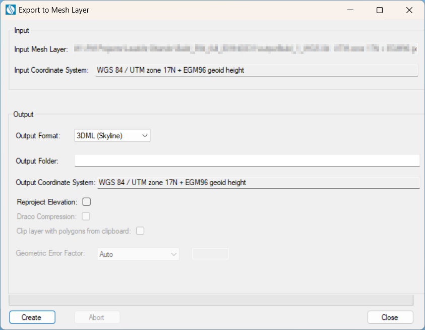
Export to Mesh Layer
2. The Input 3D Layer is automatically populated based on the layer selected in the previous step.
3. The 3D layer’s coordinate system is automatically read from the layer. If you want to change the model’s coordinate system, in the Input Coordinate System field, click Change. See "Coordinate System Dialog" in the "Basic Concepts" chapter for information.
4. Select an Output Format: Skyline 3DML, Cesium 3D Tiles, Esri I3S-SLPK, or Bentley 3MX.
5. Browse to the required Output Folder. The exported mesh layer will be saved to this folder.
6. In the Output Coordinate System, set the output mesh model’s coordinate system. This is by default set to the project’s terrain coordinate system. If you want to change the model’s coordinate system, in the Output CS field, click Change. See "Coordinate System Dialog" in the "Basic Concepts" chapter for information. 3D Tiles output is always produced in ECEF coordinate system.
7. If you want to reproject the input layer’s elevation values to the output coordinate system, select the Reproject Elevation check box. When exporting to 3D Tiles, it is recommended to select the Reproject Elevation option in order to reproject the elevation values to ellipsoid, and then to ECEF as required by the Cesium 3D Tiles standard for compatibility with other standard Cesium resources, e.g., data from terrain providers, that use ellipsoid elevation.
Note: Some Cesium resources, e.g., data from terrain providers, use geoid elevation value that were declared as ellipsoid. This data does not adhere to the Cesium standard of the ellipsoidal WGS 84 Earth-Centered, Earth-Fixed (ECEF) reference frame (EPSG 4978) coordinate system and would only match other resources, e.g., 3D Tiles, that also use such ellipsoid-declared geoid values. To export a 3D layer that is compatible with these resources, the elevation values should not be reprojected to ellipsoid, so the check box should be cleared.
8. For 3D Tiles and I3S-SLPK mesh formats, if you want to compress the mesh in Draco format for reduced size and better streaming, select Draco Compression.
9. If you want to export sections of the 3D layer using clip polygons on the clipboard, select the Clip layer with polygons from clipboard check box.
Note: Only objects with a polygon geometry, i.e., created via 2D Objects > Polygon (on the Home or Objects tab) or polygons in a feature layer are supported.
10. Click Create. The created 3DML is added to the project and displayed in the Project Tree.