Importing and converting 3D layers
The following formats can be imported and converted to 3DML:
§ BIM
In addition to the import methods supported from TerraExplorer user interface, additional import options can be performed from the SLMeshConverter command line tool. See "Importing and Exporting Using the Command Line" in this chapter for information.
OGC 3D Tiles
Importing and converting DAE (LODTreeExport.xml) mesh layers
You can import a mesh layer in DAE (LODTreeExport.xml) format from older versions of PhotoMesh and other software and convert it to a stream-optimized 3DML.
To import and convert a DAE mesh layer:
1. On the Layers tab, in the 3D Layer group, click the arrow next to Load 3D Layer, and select Import DAE Layer. The Import Mesh and Convert to 3DML dialog is displayed.
2. Browse to the DAE layer you want to import (LODTreeExport.xml) and click Open. The Import Mesh and Convert to 3DML dialog is displayed.
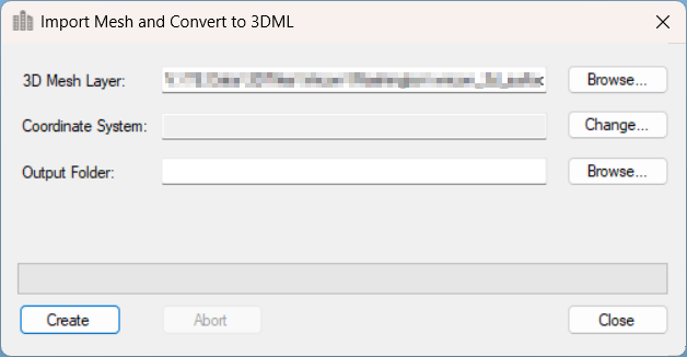
Import DAE Mesh and Convert to 3DML
3. The mesh model’s coordinate system is automatically read from the imported file. If you want to change the model’s coordinate system, click Change. See "Coordinate System Dialog" in the "Basic Concepts" chapter for information.
4. Browse to the required Output Folder. The converted mesh model will be saved to this folder.
5. Click Create. The created 3DML is added to the project and displayed in the Project Tree.
Importing and converting OpenScene Graph (OSGB) layers
OSGB mesh layers are the native format of the open-source – OpenSceneGraph library http://www.openscenegraph.org/. OSGB layers created in an external application can be imported and converted to the stream optimized, 3DML mesh layer format. See "Uploading Layers to SkylineGlobe Server" in the "Working with SkylineGlobe Server" chapter.
The *.filelist.txt file format is supported for the import and conversion of multiple OSGB tiles into a single 3DML. To use this format, a [FileName].filelist.txt text file should be created that references each of the OSGB tiles to be included in the 3DML. This file must adhere to the following rules:
§ One tile should be referenced per line with the relative path to that tile’s root file in the folder, e.g., ./Tile_485_494/georef/georef.osgb
§ The path is relative to the filelist.txt file
For example, if you have four OSGB tile folders:
§ Tile_485_494
§ Tile_485_495
§ Tile_486_494
§ Tile_486_495
All of these folders should be placed in a directory next to the *.filelist.txt file, and then referenced as follows in the Example.filelist.txt file:
./Tile_485_494/georef/georef.osgb
./Tile_485_495/georef/georef.osgb
./Tile_486_494/georef/georef.osgb
./Tile_486_495/georef/georef.osgb
To import and convert an OSGB mesh layer:
1. On the Layers tab, in the 3D Layer group, click the arrow next to Load 3D Layer, and select Import OpenScene Graph Layer.
The Import Mesh and Convert to 3DML dialog is displayed.
2. Browse to the OSGB layer you want to import (*.osgb or *.filelist.txt), and click Open. The Import Mesh and Convert to 3DML dialog is displayed.
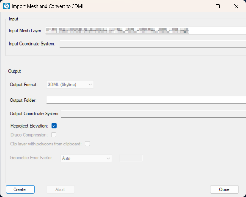
Import Mesh and Convert to 3DML
3. The Input Mesh Layer is automatically populated based on the OSGB layer selected in the previous step.
4. The mesh model’s coordinate system is automatically read from the imported file. If you want to change the model’s coordinate system, in the Input Coordinate System field, click Change. See "Coordinate System Dialog" in the "Basic Concepts" chapter for information.
Note: The coordinate system and model center information can be read from a metadata.xml file that is placed next to the *.filelist.txt file. The metadata.xml can be obtained or generated from PhotoMesh or manually generated. See "Metadata XML File" in this chapter for information on creating this file.
5. Browse to the required Output Folder. The converted mesh model will be saved to this folder.
6. In the Output Coordinate System, set the output mesh model’s coordinate system. This is by default set to the project’s terrain coordinate system. If you want to change the model’s coordinate system, in the Output CS field, click Change. See "Coordinate System Dialog" in the "Basic Concepts" chapter for information.
7. If you want to reproject the input layer’s elevation values to the output coordinate system, select the Reproject Elevation check box.
8. If you want to import sections of the mesh layer using clip polygons on the clipboard, select the Clip layer with polygons from clipboard check box.
Note: Only objects with a polygon geometry, i.e., created via 2D Objects > Polygon (on the Home or Objects tab) or polygons in a feature layer are supported.
9. A correction factor sometimes must be applied to a layer’s geometric error value so that the 3DML will display properly in TerraExplorer. Geometric error together with other properties allow the viewer to determine the optimal balance between quality and performance so that the best Level of Detail (LOD) for the current view can be used. In the Geometric Error Factor field, select Auto to automatically calculate the factor for optimal display in TerraExplorer.
10. Click Create. The created 3DML is added to the project and displayed in the Project Tree.
Creating a metadata XML file
The metadata.xml file that georeferences an OSGB model in TerraExplorer must include the following information:
§ Full WKT of the model's coordinate system (<SRS> tag) (You can use the coordinate system dialog that opens when importing the mesh to generate the full WKT)
§ Pivot coordinates (<SRSOrigin> tag)
Download sample: metadata.xml.
<?xmlversion="1.0" encoding="utf-8"?>
<ModelMetadata version="1">
<!--Spatial Reference System-->
<SRS>PROJCS["WGS 84 / UTM zone 30N",
GEOGCS["WGS 84",
DATUM["WGS_1984",
SPHEROID["WGS 84",6378137,298.257223563,
AUTHORITY["EPSG","7030"]],
AUTHORITY["EPSG","6326"]],
PRIMEM["Greenwich",0,
AUTHORITY["EPSG","8901"]],
UNIT["degree",0.0174532925199433,
AUTHORITY["EPSG","9122"]],
AUTHORITY["EPSG","4326"]],
PROJECTION["Transverse_Mercator"],
PARAMETER["latitude_of_origin",0],
PARAMETER["central_meridian",-3],
PARAMETER["scale_factor",0.9996],
PARAMETER["false_easting",500000],
PARAMETER["false_northing",0],
UNIT["metre",1,
AUTHORITY["EPSG","9001"]],
AXIS["Easting",EAST],
AXIS["Northing",NORTH],
AUTHORITY["EPSG","32630"]]</SRS>
<!--Origin in Spatial Reference System-->
<SRSOrigin>466326.000,5618961.000,-19.000</SRSOrigin>
<Texture>
<ColorSource>Visible</ColorSource>
</Texture>
</ModelMetadata>
Importing and converting OGC 3D Tiles (tileset.json) layers
3D Tiles mesh layers can be imported and converted to the stream optimized, 3DML mesh layer format. TerraExplorer supports both refinement modes (ADD and REPLACE) and is compatible with 3D Tiles version 1.0 (B3DM 2.0) and version 1.1 (GLB 2.0). See "Uploading Layers to SkylineGlobe Server" in the "Working with SkylineGlobe Server" chapter.
To import and convert a 3D Tiles mesh layer:
1. On the Layers tab, in the 3D Layer group, click the arrow next to Load 3D Layer, and select Import 3D Tiles Layer.
The Import Mesh and Convert to 3DML dialog is displayed.
2. Browse to the 3D Tiles layer you want to import, and click Open. The Import Mesh and Convert to 3DML dialog is displayed.
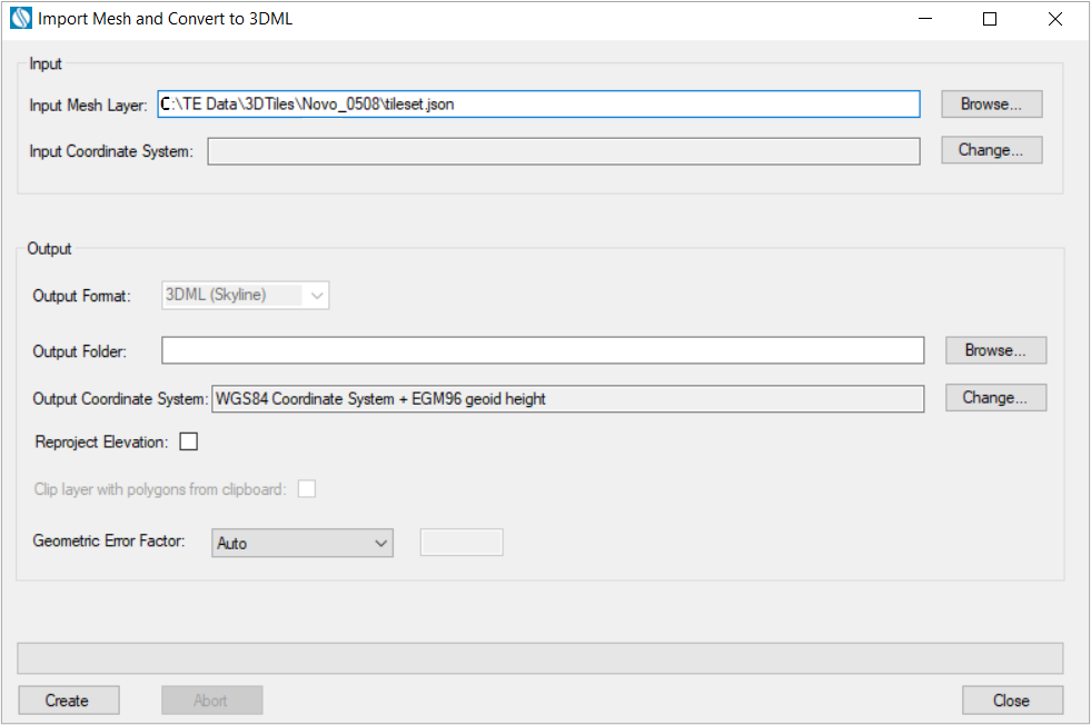
Import Mesh and Convert to 3DML
3. The Input Mesh Layer is populated based on the 3D Tiles layer selected in the previous step and the mesh model’s Input and Output Coordinate Systems are automatically set to ECEF.
4. Browse to the required Output Folder. The converted mesh model will be saved to this folder.
5. If you want to reproject the input layer’s elevation values to the output coordinate system, select the Reproject Elevation check box. Most 3D Tiles use ellipsoid elevation as required by the Cesium 3D Tiles standard, so it is recommended to reproject them to the vertical coordinate system of the terrain.
Note: Some 3D Tiles are created by reprojecting geoid elevation values declared as ellipsoid, into Earth-Centered, Earth-Fixed (ECEF). These 3D Tiles do not adhere to the 3D Tiles standard of the ellipsoidal WGS 84 ECEF reference frame (EPSG 4978) coordinate system and will only match other resources, e.g., data from terrain providers that use such ellipsoid-declared geoid values. To convert such 3D Tiles to ellipsoid-declared 3DML with correct geoid values, select WGS84 Lat-Long ellipsoid (4326) as the output, and select the Reproject Elevation check box. After the import process is complete, open these 3DML’s property sheets and clear their Reproject Elevation check boxes, so their geoid values are not reprojected.
After completing the import process, you can further convert the 3DML to geoid-declared mesh layers (with geoid values): by exporting the 3DML to 3DML format using the Export to Mesh tool. Set both the Input and Output Coordinate Systems to WGS84 Coordinate System + EGM96 geoid height, and select Reproject Elevation, to override the elevation coordinate system that was previously declared incorrectly.
6. If you want to import sections of the mesh layer using clip polygons on the clipboard, select the Clip layer with polygons from clipboard check box.
Note: Only objects with a polygon geometry, i.e., created via 2D Objects > Polygon (on the Home or Objects tab) or polygons in a feature layer are supported.
7. A correction factor sometimes must be applied to a layer’s geometric error value so that the 3DML will display properly in TerraExplorer. Geometric error together with other properties allow the viewer to determine the optimal balance between quality and performance so that the best Level of Detail (LOD) for the current view can be used. Select Auto to automatically calculate the factor for optimal display in TerraExplorer.
8. Click Create. The created 3DML is added to the project and displayed in the Project Tree.
Importing and converting BIM layers
Building Information Modeling (BIM) layers store the geographic location and attribute data of models. When these files are imported into TerraExplorer, they are automatically converted to high-resolution, textured, 3DML models that have been compressed and stream-optimized to accelerate loading speed and efficiently handle memory. Currently, TerraExplorer supports IFC versions: 2x3, 4, 4x1, 4x2, and 4x3 (rc1,rc2, Add2). IFC (Industry Foundation Classes) is an openly documented standard for the exchange of data. It is a platform neutral, open file format specification that is not controlled by a single vendor or group of vendors.
While IFC is the recommended BIM format, TerraExplorer continues to support FBX for legacy workflows. FBX is a proprietary Autodesk format designed primarily for interoperability between 3D content creation applications. Since no new FBX import libraries are being added, newer FBX models may not be fully supported.
To import BIM layers:
1. On the Layers tab, in the 3D Layer group, click BIM. The Import BIM and Convert to 3DML dialog is displayed.
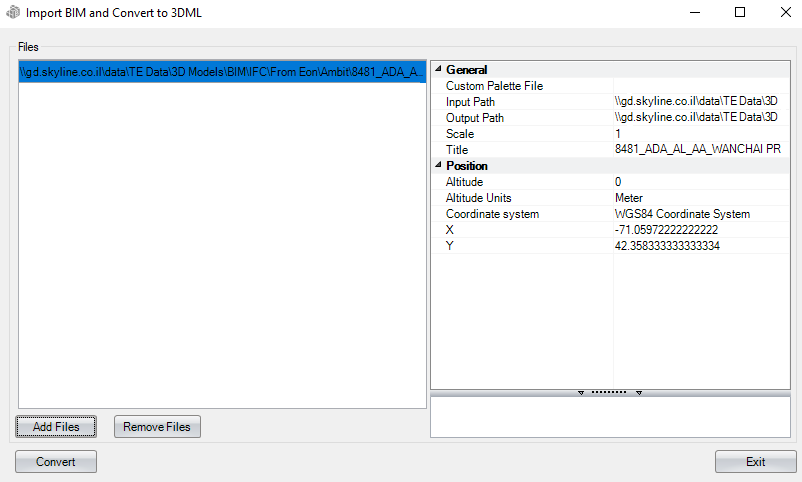
Import BIM and Convert to 3DML Dialog
2. Click Add Files. The Open dialog is displayed.
3. Browse to the required files, and click Open. All files added to the project are listed in the File section of the dialog.
Note: Only IFC 2x3, 4, 4x1, 4x2, and 4x3 (rc1,rc2, Add2) and Autodesk Revit FBX versions 7.5, 7.4, 7.3, 7.2, 7.1, 7.0, 6.1, and 6.0 files are supported. The loading process can take some time since the files are analyzed before they are loaded.
4. From the File section of the dialog, select the file whose properties you want to modify. Use CTRL-click or SHIFT-click to multi-select. Using the property sheet, set the BIM layer properties as required. See "Setting and Editing BIM Layer Properties" in this chapter for information.
5. Click Convert. If any of the selected files were already converted to 3DML, a dialog is displayed asking if you want to rebuild models for the files. Click Yes to rebuild. The tool converts the IFC file to a 3DML. When conversion is complete, a dialog is displayed informing you of the successful conversion, and the 3DML model is added to the Project Tree.
BIM import settings
|
General |
|
|
Custom Palette File |
An XML file that assigns different colors to different materials. To modify these color assignments, use the BimAttributes.xml file located under the TE application files (.\Program Files\Skyline\TerraExplorer Pro\Resources) as your template and edit as required. This field is unavailable for IFC models, which already include color representation information. |
|
Input Path |
Full path of the BIM file. |
|
Output Path |
Full path of the model file that will be created when the BIM is converted to 3DML. |
|
Scale |
Scale of the model. This property is usually used to scale a model to the metric units used in TerraExplorer, if the model uses a different measurement system or units. If you select the units of your model, the suggested scale is automatically displayed. |
|
Title |
3DML layer name as it will appear in the Project Tree. |
|
Position |
|
|
Altitude |
Absolute altitude of the BIM model. |
|
Altitude Units |
The z-coordinate units of measurement in which the model was created. |
|
Coordinate System |
Determines the coordinate system of the X and Y coordinates. Click Set to open the Coordinate System dialog. |
|
X |
X-coordinate of the pivot of the BIM model. |
|
Y |
Y-coordinate of the pivot of the BIM model. |
|
MGRS |
The coordinates of the pivot of the BIM model in Military Grid Reference System (MGRS) coordinates. This field is only available if Show MGRS Coordinates was selected in the Options dialog. See "View" in the "Using TerraExplorer Options" chapter for more information. |
Importing and exporting 3D layers using the command line
In addition to the format conversions supported from TerraExplorer user interface, additional conversions can be performed from the SLMeshConverter command line tool:
§ 3D Tiles to: 3D Tiles, I3S/SLPK, 3MX, and o3DML
§ OSGB to: 3D Tiles, I3S/SLPK, 3MX, and o3DML
§ o3DML to o3DML
§ 3DML to o3DML
§ 3DML to LAS/LAZ
To convert, construct a single command line that includes all the following:
1. Run SLMeshConverter
"c:\program files\Skyline\TerraExplorer Pro\SLMeshConverter.exe" -cmd convert
2. Define the input layer:
§ For 3DML/o3DML – Full path to the file
§ For 3D Tiles – Full path to the tileset.json
§ For OSGB – Full path to the root OSGB file
-in "FullPathToFile"
3. -Define the output format:
§ For 3DML
-f 3dml
§ For 3D Tiles
-f b3dm
§ For o3DML
-f b3dm -m 2
§ For I3S
-f i3s
§ For SLPK
-f i3s -m 2
§ For 3MX
-f 3mxb
§ For LAS/LAZ
-f las
Note: The LAS/LAZ distinction is determined by the -out file name extension.
4. Set the output WKT by defining the path to a file containing the WKT in a single line. If this parameter is not provided, the output will be in the same coordinate system as the input layer. WKT is a text file with the well known text in it.
-wktout "C:\WKTFiles\4326.wkt"
5. Specify the path to the output folder or file:
§ Folder output – For formats that generate a folder structure (e.g., 3MX, 3D Tiles), specify the full path to the output folder. E.g.,
-out "C:\ConvertedLayers"
§ File output – For formats that generate a single file, specify the full path to the output file, including the appropriate file extension (e.g., .3dml, .slpk, .osgb, .las, .laz). E.g.,
-out "C:\ConvertedLayers\outputfile"
Note: For OSGB, specify the full path to the root OSGB file. E.g.,
-out "C:\ConvertedLayers\Tile_000106_000090.osgb"
Examples:
Convert 3DML to 3D Tiles
"C:\Program Files\Skyline\TerraExplorer Pro\SLMeshConverter.exe" -cmd convert -in "D:\Pune_Block_10_Build_2_ATGCP01.3dml" -out "C:\Data\Tileset.json" -f b3dm
Convert 3D Tiles to o3DML
"C:\Program Files\Skyline\TerraExplorer Pro\SLMeshConverter.exe" -cmd convert -in "C:\Data\Tileset.json" -out "D:\Pune_Block_10_Build_2_ATGCP01.o3dml" -f b3dm -m 2
Convert o3DML to i3s
"C:\Program Files\Skyline\TerraExplorer Pro\SLMeshConverter.exe" -cmd convert -in "C:\Data\model.o3dml" -out "D:\model" -f i3s
Conversion methods
|
|
Output Formats |
|||||||
|
Input Formats |
|
3DML |
o3DML |
3D Tiles |
Esri I3S/SLPK |
Bentley’s 3MX |
Models (DAE, OBJ, GLB, FBX) |
LAS/LAZ |
|
3DML/o3DML |
Command Line |
|||||||
|
3D Tiles |
Command Line |
Command Line |
Command Line |
Command Line |
||||
|
OSGB |
Command Line |
Command Line |
Command Line |
Command Line |
Indirect* |
Indirect* |
||
|
DAE LODTreeExport |
Indirect |
Indirect |
Indirect |
Indirect |
Indirect* |
Indirect* |
||
|
BIM FBX |
Indirect |
Indirect |
Indirect |
Indirect |
N/A |
N/A |
||
|
BIM IFC |
Indirect |
Indirect |
Indirect |
Indirect |
N/A |
N/A |
||
|
Point layer with models (DAE, OBJ...) |
Indirect |
Indirect |
Indirect |
Indirect |
N/A |
N/A |
||
Legend:
§ User Interface - Direct conversion via user interface
§ Command Line - Direct conversion (via SLMeshConverter command line tool)
§ Indirect – Indirect conversion – first convert to 3DML/o3DML and from 3DML/o3DML to the required format
§ N/A – Not supported
§ * - Only for PhotoMesh-generated meshes
Importing BIM Models Using the Command Line
In addition to importing BIM models through the TerraExplorer user interface, IFC and FBX files can also be converted to 3DML using the ImportFBXTool command-line utility. This tool enables automated conversion workflows and integration with external applications.
During execution, the command-line tool outputs status information:
§ Progress messages are returned through stdout
§ Errors are returned through stderr
§ Successful execution returns exit code 0
This command-line process can also be executed through the TerraExplorer API using the SGWorld.Creator.CreateCommandLineProcessAsync method.
To convert a BIM model, construct a single command line that includes the following:
1. Run ImportFBXTool:
"C:\Program Files\Skyline\TerraExplorer Pro\ImportFBXTool.exe"
2. Specify the full path to the IFC or FBX input file to convert (mandatory).
-in "FullPathToFile"
3. Define the output file. Specify the output path and filename for the converted 3DML file (optional).
-out "C:\ConvertedFiles\outputfile.3dml"
Note: If this parameter is not provided, this defaults to the same location as the input file using the same file name with a .3dml extension.
4. Set the scaling factor applied to the model (optional, default is 1):
-scale 1
5. Define the geographic location and altitude of the model. If not specified, the location values defined in the source file are used (optional).
-x Longitude
-y Latitude
-altitude HeightValue
-altitudeUnits meter | feet
6. Set the output WKT by defining the full path to a file containing the WKT. If this parameter is not provided, the output will be in the same coordinate system as the input IFC file when available. Otherwise, a default ENU (0,0) coordinate system is used (optional).
-wkt "C:\WKTFiles\4326.txt"
7. Define a title to assign to the converted 3DML model (optional):
-title "ModelTitle"
Example:
"C:\Program Files\Skyline\TerraExplorer Pro\ImportFBXTool.exe" -in "D:\BIM\Models\Building.ifc" -out "D:\ConvertedModels\Building.3dml" -scale 1 -x 32.1304561 -y 34.8128558 -altitude 100 -altitudeUnits meter -wkt "D:\WKTFiles\4326.txt" -title "Building Model"
Converting models to 3DML
The Convert Models to 3DML tool enables you to create a unified, stream optimized 3D Mesh Layer (3DML) database from a point feature layer with individually referenced 3D model files. This tool is only recommended for converting layers with many small models (each model should not exceed 100 MB), e.g., a city with individually modeled buildings. For larger model files, it is recommended to export the mesh models in a format that supported by TerraExplorer, and then to import them. See "Streaming 3D Models Using Feature Layers" in the "Feature Layers" chapter and "Importing and Converting 3D Layers" in this chapter for information. Conversion to 3DML improves performance and provides better support for web and mobile devices, especially for large layers that reference many different models. If your point feature layer references multiple instances of only a few models, conversion to 3DML is not recommended.
To create a 3DML dataset:
1. On the Layers tab, in the 3D Layer group, click Models to 3DML. The Convert Models Layer to 3DML dialog is displayed, showing a list of all shapefile, sqlite, and GeoPackage point feature layers in the project with individually referenced 3D model files. It may take a short while for the list of layers to be displayed.
Note: Model textures should not exceed 4096 × 4096 pixels.
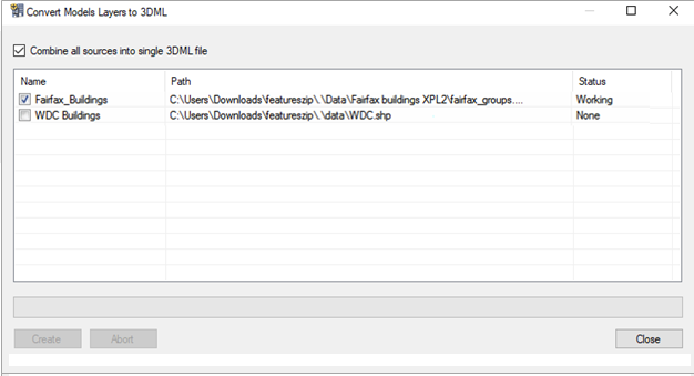
Convert Models Layer to 3DML
2. Select the files for which you want to create 3DML layers, and click Create.
Note: You can click Abort at any point to cancel 3DML creation.
3. If you want to combine all sources into a single 3DML, select the check box.
4. When the 3DML layers have been created, a dialog is displayed informing you that the 3DML layers will now be loaded into the project, and asking you if you want to remove the corresponding feature layers that they were based on. Click Yes to remove them, or click No to leave them in the project.