Other navigation tools and options
Oculus Rift and Meta Quest controls
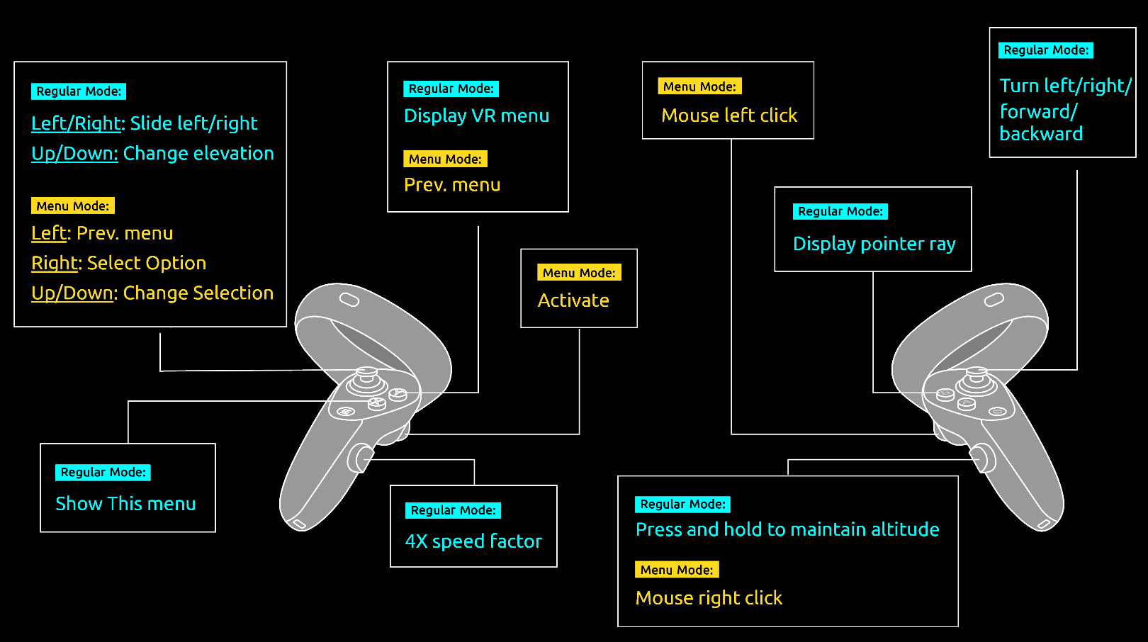
Navigate intuitively through Skyline’s 3D World and perform most TerraExplorer commands using the Oculus Rift (Rift and Rift S) and Meta Quest (Quest, Quest 2, Quest Pro, and Quest 3) controllers. See "Standard Layouts" in the "Basic Concepts" chapter for information on switching the TerraExplorer layout to the Oculus VR option.
|
Action |
Oculus Rift and Meta Quest Controls |
|
Navigation |
|
|
Slide left and right |
Move left thumbstick left and right (Regular mode). |
|
Change elevation |
Move left thumbstick forward and backward (Regular mode). |
|
Turn left/right/forward/backward |
Move right thumbstick (Regular mode). |
|
Maintain current altitude |
Press and hold grip on right controller (Regular mode). |
|
Accelerate |
Press and hold grip on left controller (Regular mode). |
|
Cast ray from your hand controller to the 3D virtual world |
Press B button on right controller (Regular mode). |
|
Menus |
|
|
Open the previous menu |
Press Y button on left controller (Menu mode) OR move left thumbstick left (Menu mode). |
|
Close menu if displaying root menu |
Press Y button on left controller (Menu mode) |
|
Change menu selection |
Move left thumbstick forward and backward (Menu mode). |
|
Activate selected menu item |
Press trigger on left controller (Menu mode) OR Move left thumbstick right (Regular mode). |
|
Left-click |
Press trigger on right controller. |
|
Right-click |
Press grip on right controller. |
Look around tool
The Look Around tool serves as a virtual stationary observation deck, enabling you to analyze the view from a specific position. Using the controls, you can easily adjust your direction and tilt and zoom in and out.
To use the Look Around tool:
1. On the Navigation tab, in the Navigation Aid group, click Look Around. The Look Around controls are displayed.
Look Around Controls
2. Move the slider to adjust the zoom. The distance between the viewer position and the center of the screen is displayed in the bottom right corner.
Note: When the Look Around tool is opened, the navigation mode is automatically switched to Turn and Tilt. See "Navigating in the Turn and Tilt Mode" in this chapter. You can change the mode as required.
Underground navigation
The underground navigation mode allows you to explore the subsurface of the terrain. You can navigate under the terrain’s surface and through buildings. A subsurface grid navigation aid appears when you navigate below the terrain, allowing you to navigate the same way as above ground.
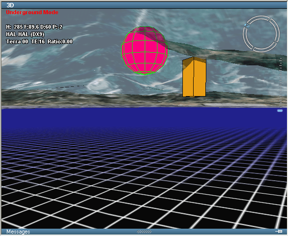
Navigating in Underground Mode
To fly in underground mode:
1. On the Home tab, in the Navigation group, click Underground Mode.
2. Use any of the techniques mentioned above to navigate in the 3D environment. You can freely go through the terrain surface in any direction.
First-person navigation mode
The Walk Mode lets you navigate through the 3D world as if you are walking through it, maintaining a constant altitude as you move. This mode is used in particular for navigation indoors. Its x-ray vision and collision detection controls make it easier to navigate within confined spaces and direction control buttons provide for greater control and finer adjustments to movement.
To navigate in Walk Mode:
1. On the Home tab, in the Navigation group, click Walk Mode. The Walk Mode Navigation dialog is displayed.
Walk Mode Navigation
2. If you want to navigate outdoors, click Start.
3. If you want to navigate indoors, click the building you want to enter. This building can be any 3D model (e.g., 3dml, .x, .xpl, .dae or .flt) and include interior modeling of the different floors and rooms.
4. After clicking on the building entry location or the dialog link, navigation controls are displayed.
Note: Collision detection is automatically turned on and navigation mode automatically switches to Slide mode. Collision detection can be switched off from the Walk Mode Navigation panel, while Slide mode can be switched off from the Navigation tab.
Walk Mode Navigation Controls
5. Navigate using the navigation controls:
|
Control |
Description |
|
Control |
Description |
|
|
Turn counterclockwise |
|
|
Toggle collision detection on and off. When collision detection is on, any collision with a solid structure, i.e., any object whose fill opacity is greater than 50%, while navigating within the 3D model, will stop movement. Note: Collision detection can also be toggled on and off from the Navigation tab. |
|
|
Forward |
|
||
|
|
Turn clockwise |
|
|
Toggle x-ray vision on and off. When x-ray vision is on, the model becomes semi-transparent, enabling you to see through all model walls. |
|
|
Up |
|
||
|
|
Left |
|
|
Adjusts the field of view. |
|
|
Backward |
|
||
|
|
Right |
|
|
Exit from walk mode |
|
|
Down |
|
|
|


6. If you want to exit from walk mode, on the Home tab toggle off the Walk Mode command or click the x in the Walk Mode Navigation control panel.
Navigation map
The Navigation Map window provides quick and easy navigation through the entire terrain. It shows a raster-based map and the location and direction of the camera view on the map. The Navigation Map window offers a simple mechanism to integrate file or server-based maps into the application.
The Navigation Map supports the same file formats and servers as are supported for raster layers. See "Loading Raster Layers" in the "Imagery and Elevation Layers" chapter for information.
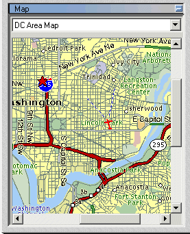
The Navigation Map Window
Current Location Indicator
The Navigation Map marks the camera’s location and field of view. The indicator shows the direction of the flight in the 3D Window as a red plane icon, and the direction and field of the camera’s view as two blue lines.

Location Indicator
By default, the indicator is in the center of the Navigation Map. If the cursor is located near the edge of the map, the location indicator may be off the center.
If the cursor is currently located outside the area of the map, the location indicator is not present.
Using the Navigation Map
If the Navigation Map is not displayed, on the View tab, in the Show/Hide group, select the Navigation Map check box.
Selecting a navigation map
The Navigation Map window can contain more than one map for the same project. At the top of the Map Window, select the required Navigation Map from the dropdown list of available maps.
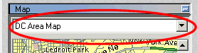
Select Map
Moving to any location on the terrain
Using a Navigation Map, you can jump directly to any place on the terrain.
To move to any location on the terrain, do either of the following:
§ Double-click on any area of the navigation map to jump directly to the chosen location.
or
§ Right-click on the required spot on the map, and select Jump from the shortcut menu.
The view in the 3D Window is synchronized with the plane indicator position on the navigation map.
To turn-off synchronization:
§ Right-click the map area, and toggle off the Synchronize 3D option.
Adding a navigation map to the navigation map window
To add new maps to the Navigation Map window:
1. On the Navigation tab, in the Map group, click Map. The Navigation Map Settings dialog is displayed.
Navigation Map Settings
2. Click Add. The Open dialog is displayed.
3. Browse to the required map and click Open.
Note: The Navigation Map supports the same file formats and servers as are supported for raster layers. See "Loading Raster Layers" in the "Imagery and Elevation Layers" chapter for information. It is strongly recommended to use a compressed format (JPEG or GIF) and not BMP, for Navigation Maps. This ensures maximum performance with slower Internet connections.
4. In the Navigation Map Settings dialog, define the property sheet parameters as required.
5. If the map is not referenced to the coordinate system of the terrain, do either of the following:
§ Reprojection - When the map is referenced to a different coordinate system than the coordinate system of the terrain. See "Reprojecting a Navigation Map" in this chapter for further information.
§ Manual Adjustment - When the map is not referenced to any coordinate system. See "Adjusting a Navigation Map Manually" in this chapter for further information.
Reprojecting a navigation map
When the navigation map is referenced to a coordinate system, which is different from the terrain coordinate system, the map must be reprojected.
To reproject a map:
1. On the Navigation tab, in the Map group, click Map. The Navigation Map Settings dialog is displayed.
2. In the Maps section, select the required map.
3. In the Projection section of the property sheet, in the Reproject Source, select Yes to enable reprojection of the source.
4. In the Coordinate System field, click Set. The Coordinate System dialog opens. Enter the source file’s coordinate system information. See "Coordinate System Dialog" in the "Basic Concepts" chapter for information.
5. Click OK.
Adjusting a navigation map manually
Adjusting a navigation map manually is required when the navigation map is not referenced to any coordinate system. The manual adjustment is performed by pairing map locations with their terrain counterparts.
To manually adjust a navigation map, do the following:
1. On the Navigation tab, in the Map group, click Map. The Navigation Map Settings dialog is displayed.
2. In the Maps section, select the required map.
3. In the Imagery section of the property sheet, in the Manual Adjustment field, click Set. The Navigation Map Settings dialog is minimized.
Note: If you want to restore the Navigation Map Settings dialog, double-click its title bar.
4. Enter the first map point by right-clicking on the map and selecting Add Map Tie Point from the shortcut menu.
5. Enter the matching terrain point by right-clicking in the 3D Window and selecting Add Terrain Tie Point from the shortcut menu.
6. Repeat the steps above for the second and third location matches. The Navigation Map Settings dialog is restored. Click OK to set the terrain points and close the dialog.
Setting the maps order in the navigation maps window
You can set the order of the maps as they appear in the dropdown list of available maps in the Navigation Maps window.
To set the order of the maps:
1. On the Navigation tab, in the Map group, click Map. The Navigation Map Settings dialog is displayed.
2. Select the map you wish to move up or down the list.
3. Click the arrow buttons until the map is moved to the desired position on the list.
Deleting a navigation map from a project
To delete a navigation map:
1. On the Navigation tab, in the Map group, click Map. The Navigation Map Settings dialog is displayed.
2. Select the map you wish to delete from the Maps panel.
3. Click Remove. A dialog is displayed confirming that you want to delete the selected map. Click Yes to delete or No to cancel.
Multiple coordinate systems
The Multiple Coordinate Systems tool projects the current position into multiple coordinate systems simultaneously. A display mode selector at the top of the dialog controls which position is tracked across all panels: Camera Location, Cursor Location, or Screen Center. The dialog includes Lat Long and MGRS sections, which are always included, plus an additional section where you can select another coordinate system to project the current coordinates into. You can also type a coordinate in any of the available coordinate systems to jump to that location and use the built-in Coordinate Converter to reproject between any two coordinate systems, independently of the current position in the 3D Window.
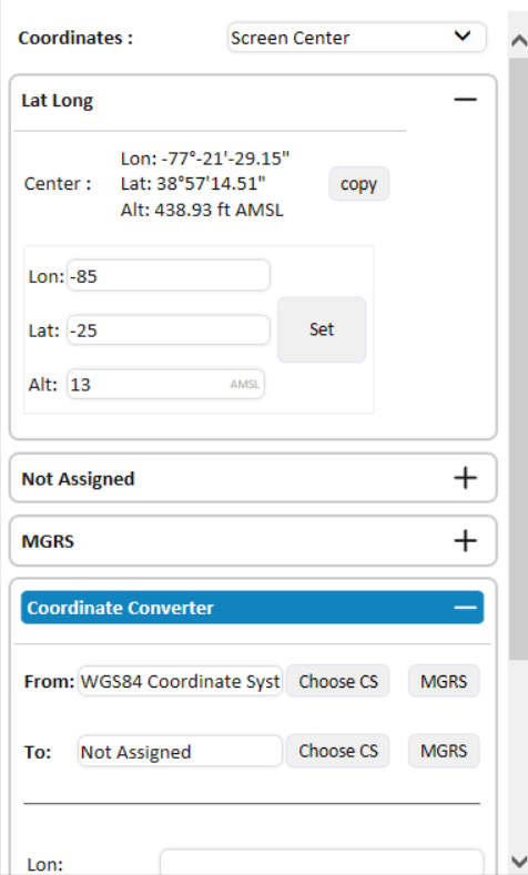
Multiple Coordinate Systems Tool
To use the Multiple Coordinate Systems tool:
1. On the Navigation tab, in the Navigation Aid group, click Multiple Coord Sys. The Multiple Coordinate Systems dialog opens.
2. Select which position to display across the dialog's coordinate system sections:
§ Camera Location - Current camera (viewpoint) position
§ Cursor Location - Position under the mouse cursor on the terrain
§ Screen Center - Position at the center of the 3D window
3. In any section (Lat Long, MGRS or a custom coordinate system), do the following:
a. To copy the coordinates of the current position, click Copy.
b. To jump to a specific location, type the location's coordinate values and click Set. The camera's landing point depends on the active display mode:
§ Camera Location mode - Jumps directly to the typed coordinate, preserving the current yaw and pitch.
§ Cursor Location or Screen Center mode – Positions the view above and behind the point so it appears at the center of the screen.
Note: The Lon/Lat input fields support multiple coordinate formats
§ Decimal degrees – 34.5 or 34.5°
§ Degrees, decimal minutes – -81° 0.001′
§ Degrees, minutes, seconds – 28° 32′ 4.604″
§ Values can be entered with N/S/E/W prefixes or suffixes
4. To add another coordinate system, in one of the Not Assigned sections, click Choose Coordinate System. The Coordinate System dialog is displayed. Enter the required information. See "Coordinate System Dialog" in the "Basic Concepts" chapter for information.
5. To reproject coordinates between any two coordinate systems, independently of the current position in the 3D Window, expand the Coordinate Converter section at the bottom of the dialog and do the following:
a. In From, the project's current coordinate system is pre-populated. To change it, clickChoose CS to select a different coordinate system, or click MGRS to use MGRS. See "Coordinate System Dialog" in the "Basic Concepts" chapter for information.
b. In To, click Choose CS to select the target coordinate system, or click MGRS to use MGRS.
c. Enter the coordinate values in the input fields. The fields adapt to the selected coordinate system: Lon/Lat for geographic systems, X/Y for projected systems, or a single text field for MGRS. Entering an altitude in Alt (AMSL) is optional and defaults to 0.
d. Click Convert. The reprojected result appears below the Convert button. If any fields contain invalid values, they flash red.
GPS tracking
The GPS Tracking tool creates 2D or 3D objects and moves them according to position information, in NMEA format that it reads directly from a GPS or communication device through a USB or COM port or from a local or remote file. The GPS tool supports multiple entities in a single device and allows fast forwarding capabilities when reading the information from files.
You can display the GPS-moving objects in a variety of 2D or 3D graphic representations and add trace lines trailing the object routes.
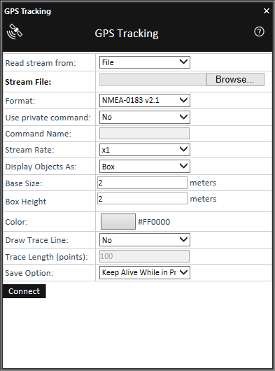
GPS Tracking Tool
To use the GPS Tracking tool:
1. On the Navigation tab, in the Navigation Aid group, click the arrow under GPS and select GPS Tracking.
2. Enter the following information:
|
Field |
Description |
|
Read stream from |
Select the location of the positioning stream. |
|
Stream File |
Select File and type the file name or click the Browse button to set the NMEA file. Select COM1, COM2, COM3 or COM4 to define the COM port where the GPS, or communication device, is connected. Note: The GPS Tracking tool supports GPS and communication devices connected to a USB port that simulate COM communication. You should select the COM port the USB driver selected when it logged in to the system. |
|
Format |
Select the format of the communication stream. The GPS Tracking currently supports only NMEA-0183 format. |
|
Use private command |
Select whether you want to use a Private command to identify the names of the different entities in a single stream. Note: If the private command tag is not set, all entities in the stream are treated as the same object. |
|
Command Name |
If you selected Yes in the Use private command field, type the name of the NMEA tag (e.g., &Pxxx) that contains the identifier of each entity. |
|
Stream Rate |
If a File was selected as the source of the stream, you can accelerate the playing of the object movements by selecting a Stream rate larger than x1. The GPS Tracking tool reads the time stamp on each entity location. When the fast-playing option is selected, the time delay between two locations, as defined in each location block Time tag, is divided by the Stream rate parameter. |
|
Display Objects As |
Select the Display Object As parameter to define the graphic representation of the GPS entities. The next parameters that display vary depending on the selected Display Object As type. |
|
Color |
Set the color for the trace line and for objects, when selecting 2D or 3D primitives. Click the Color |
|
Draw Trace Line |
Select Yes to add a trace line trailing the object. |
|
Trace Length (points) |
Set the Trace Length parameter to define the length of the line. The Trace Length defines the number of locations, preceding the current location, connected by the trace line. |
|
Save Option |
Set the Save options. § Select Delete at Disconnect to delete the objects and trace lines when the stream is finished or disconnected. § Select Keep Alive While in Project to keep the objects and trace lines in your projects until you close the FLY file. § Select Save in FLY Project to save the objects and trace lines in your FLY file. |
3. Click Connect to connect to the GPS stream. If you want to disconnect, click Disconnect.
GPX reader
GPX is an XML schema designed as a common GPS data format to describe waypoints, tracks, and routes. The GPX Reader reads GPX files and displays their waypoint and track data in the 3D Window, storing the GPX data in the project either as groups of point objects or as feature layers.
To load GPX data:
1. On the Navigation tab, in the Navigation Aid group, click the arrow under GPS, and select GPX Reader. The GPX Reader is displayed.
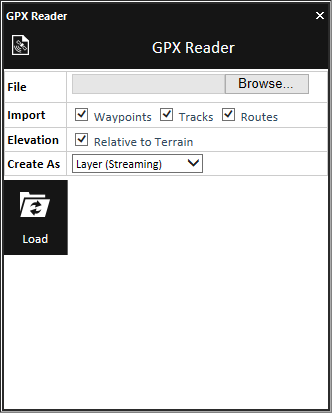
GPX Reader
2. Browse to the required GPX file.
3. Select the check boxes of the data you want to import:
§ Waypoints – The route's waypoints.
§ Tracks – The waypoints for each of the route's tracks.
§ Routes – The route’s tracks and waypoints.
4. If you want to ignore the elevation values in the GPX file, select Relative to Terrain. All waypoints and route/track polyline are displayed directly on the terrain.
5. Select one of the Create As options:
|
Option |
Description |
|
Layer If Waypoints are selected for import, a feature layer is created for all the route's waypoints. If Tracks are selected for import, then for each track in the route the following are created: § A polyline object with the track's path § A point shapefile with the waypoints of that track If Routes are selected for import, then both of the above are created. |
|
|
Layer (Streaming) |
Create streaming point shapefile layers with the route's waypoints under the application AppData. |
|
Layer (Entire) |
Create point shapefile layers with the route's waypoints under the application AppData. |
|
Group |
Create a group with waypoint objects. § A polyline object with the track's path § Image label objects for each of the track's waypoints |
6. Click Load. The GPX data is displayed in the 3D Window and a group of layers/objects is created in the Project Tree.
Target
The Target tool continuously tracks the distance and direction to a specific target.
To use the Target tool:
1. On the Navigation tab, in the Navigation Aid group, click Target. The Target dialog opens.
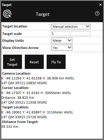
Target Dialog
2. Enter the following information:
|
Field |
Description |
|
Target Location |
Select either: § Numeric Entry § Manual Selection If you select Numeric Entry, enter the X, Y, and H values. |
|
Target Scale |
Select the type of target marking object. |
|
Display Units |
Select the display units to be used for distance/height information. |
|
Show Direction Arrow |
Select Yes if you want to display the direction-to-target arrow. |
3. Click Set Target.
4. If you are using Manual Selection as the Target-Set-Mode, click on the terrain or on any object in the 3D Window.
5. The tool displays the Camera Location, Cursor Location, Target Location and Distance from Target values according to the selected units.
6. To reset this tool, click Reset.
7. To fly to the target location, click Fly to.