Setting Advanced Aerotriangulation Parameters
Advanced aerotriangulation settings can be set when building a project or creating a new build version. When rebuilding, aerotriangulation parameters can only be set if the reconstruction step was not started in the previous build. See "Rebuilding" and "Creating a New Build Version" in this chapter for more information.
To set advanced aerotriangulation parameters:
1. Click the Aerotriangulation tab.
Advanced AT Parameters
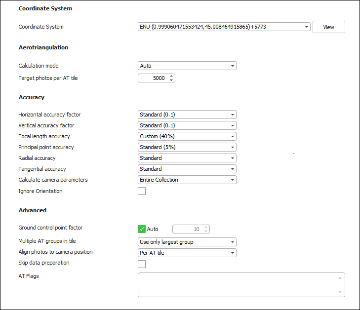
2. Set the parameters on the AT tab:
|
Parameter |
Description |
||||||||||
|
Coordinate System |
|||||||||||
|
Project’s internal coordinate system, in which the aerotriangulation and reconstruction are performed. By default, this is set to the coordinate system of the input data. If the inputted data uses multiple coordinate systems, or you want to use a different coordinate system from your input’s, select the required coordinate system. Select the Custom option to create a new custom coordinate system. See "Coordinate System" in the "Basic Concepts" chapter for more information. Note: Click View to view the full Well-Known Text (WKT) for the coordinate system. |
|||||||||||
|
Aerotriangulation |
|||||||||||
|
|
The AT calculation mode that PhotoMesh should use: § Auto – PhotoMesh automatically determines the required calculation mode. If no AT was previously performed, then PM performs a full aerotriangulation ("Calculate AT"). If an AT was previously performed, then it refines the existing AT ("Refine AT"). § Calculate AT – PhotoMesh performs a full aerotriangulation (including matching, bundle adjustment, and GCP) taking into account provided orientation and position information. All previous aerotriangulation calculations performed within PhotoMesh are ignored. § Refine AT –. PhotoMesh reruns the aerotriangulation process (performing only bundle adjustment and GCP). This option is recommended for refining the previously calculated AT or after making changes to the project that can affect the calculated AT, i.e., adding/modifying control points. § Do Not Calculate AT – PhotoMesh uses inputted camera positioning and orientation information and camera parameters (including focal length, principal point and radial/tangential distortion) without performing aerotriangulation. This option is recommended when reliable AT data in a Cartesian coordinate system, such as ENU or ECEF, is added to PM from other AT systems, e.g, Inpho and Bingo. Note: AT data in a projected coordinate system such as UTM may be unreliable either due to earth curvature or earth curvature corrections performed in the other system. This is particularly true for datasets that contain oblique photos or large frames, or cover a large geographic area. For data of this type, aerotriangulation should be re-performed in PhotoMesh, i.e., use the Refine AT option. |
||||||||||
|
Target Photos per AT Tile |
Number of photos to be included in each AT tile. The default setting of 5,000 photos is recommended for most projects and can be efficiently processed on 16 GB computers. For projects requiring more than 5,000 photos per AT tile, the the following RAM guidelines are recommended. Note that the actual RAM needed may be up to twice the suggested amount, varying based on the type of collection, inputted photo information, and specific settings used.
Certain settings or AT-related presets may require more RAM than recommended above. E.g., it is recommended to set the Target Photos per AT Tile to 30% less than the value recommended above in both of the following scenarios: § When using the aggressive match preset § When photo overlap is higher than 75% When running a large AT, it is highly recommended to leave the CPU free of other processes, since the AT process utilizes a large percentage of the available processing power. PhotoMesh includes photos in an AT tile based on the photos' frustum, if orientation information is available, or based on its position and effective range in cases where no orientation information is provided. If the effective range is large and there is a very high overlap of photos, it may be advisable to set the orientation filter to Auto. This filter will try to accelerate the AT process by filtering out photos after a rough calculation of their orientation before proceeding with the remaining aerotriangulation steps. See "Collection Property Sheet" in the "Photo Management" chapter for information about the effective range property. See "Setting Advanced Aerotriangulation Parameters" in the "Building" chapter for more information about the orientation filter. Larger AT tiles with more photos may be necessary if the default AT tiles have fewer than five ground control points that fall in or close to each tile, as is recommended for good accuracy. See the "Control Points" chapter for more information. Note: An AT with a large number of photos may take many hours to complete, and if interrupted will need to be rebuilt. |
||||||||||
|
Accuracy The accuracy of each collection's position and orientation data is set in the collection's property sheet in the Accuracy section. There, you have the option to either input custom values or to select the "Use build settings" alternative to apply the general accuracy settings set in this dialog. If some collections have custom settings, a red notification will display in this dialog informing you of this. |
|||||||||||
|
Horizontal Accuracy Factor |
Weight to assign to the photos’ provided XY coordinates in determining the calculated XY values. This ranges from Very High - External AT (Factor = 10) to Unreliable (Factor = 0). |
||||||||||
|
Vertical Accuracy Factor |
Weight to assign to the photos’ provided altitude in determining the calculated altitude value. This ranges from Very High - External AT (Factor = 10) to Unreliable (Factor = 0). |
||||||||||
|
Focal Length Accuracy |
A percentage that indicates the allowable deviation from the provided focal length value when calculating the AT. This represents the accuracy of the provided focal length. This ranges from Use Input Value to Unreliable. |
||||||||||
|
Principal Point Accuracy |
A percentage that indicates the allowable deviation from the provided principal point when calculating the AT. This represents the accuracy of the provided principal point. This ranges from Use Input Value to Unreliable. |
||||||||||
|
Radial Accuracy |
Camera's radial accuracy. It is generally recommended to select the "Standard" option. If your data was captured with a professional camera that automatically applied a radial distortion correction (i.e., the original distortion value is extremely accurate), select "Use input value". |
||||||||||
|
Tangential Accuracy |
Camera's tangential accuracy. It is generally recommended to select the "Standard" option. If your data was captured with a professional camera that automatically applied a tangential distortion correction (i.e., the original distortion value is extremely accurate), select "Use input value". |
||||||||||
|
Method of calculating the camera’s intrinsic parameters. § Entire collection – Calculate the AT so that the camera intrinsic properties are the same for all photos in the collection. § Per photo – Calculate the camera intrinsics individually for each photo in the collection. Note: Parameters should be calculated per photo when not all of a collection’s photos were taken by the same physical camera with identical focal length and principal point. |
|||||||||||
|
Ignore Orientation |
Select the check box to ignore the provided orientation value. |
||||||||||
|
Advanced |
|||||||||||
|
Ground Control Point Factor |
Weight factor to assign to the ground control points (0-10000) when performing the aerotriangulation. Select Auto to use the default value of 1000. |
||||||||||
|
Multiple AT Groups in Tile |
Select whether to include only a tile’s largest AT group (photo block) or all AT groups in AT Calculated Photos. |
||||||||||
|
Align Photos to Camera Position |
Select one of the following options: § Per AT Tile – Each AT tile is individually aligned to its respective camera positions and ground control points. This option is recommended for projects where most of the AT tiles have enough control points (generally 3 or more) to provide a reliable basis for adjusting the tile's position. Those AT tiles with fewer than three points are adjusted in relation to stable tiles which have an adequate number of control points. This option is recommended for projects with accurate camera positions as well as for nadir and corridor (linear) projects (e.g., roads or rivers) where the AT tile may come out arched. § Entire Project – The entire project is aligned as a single block to the camera positions and ground control points. This option is recommended for projects where very few of the AT tiles have sufficient control points (3 or more) to provide a reliable basis for adjusting the tile's position. |
||||||||||
|
Skip Data Preparation |
When this option is selected, PhotoMesh skips the data preparation step entirely, saving the time that would otherwise be necessary to verify that it had been performed. Only select this option if this step was previously performed, and there has been no change to the AT area or to the project. |
||||||||||
|
AT Flags |
Flags that specify alternate behaviors and settings that PhotoMesh should apply. These flags can be obtained from Skyline support. |
||||||||||
3. Click the Reconstruction tab to set advanced reconstruction parameters (see "Setting Advanced Reconstruction Parameters" in this chapter), or click Build to open PhotoMesh Build Manager to start processing (see "Monitoring a Build" in this chapter).