PhotoMesh Workflow
PhotoMesh converts standard 2D photographs into high-resolution, textured, 3D mesh models in a streamlined, step-by-step process:
§ Step 2: Creating a PhotoMesh Project
§ Step 3: Loading Photos and Other Input Sources and Preparing the Project
§ Step 4: Managing Local, Pool, and AWS Fusers
§ Step 6: Managing and Reviewing the Build
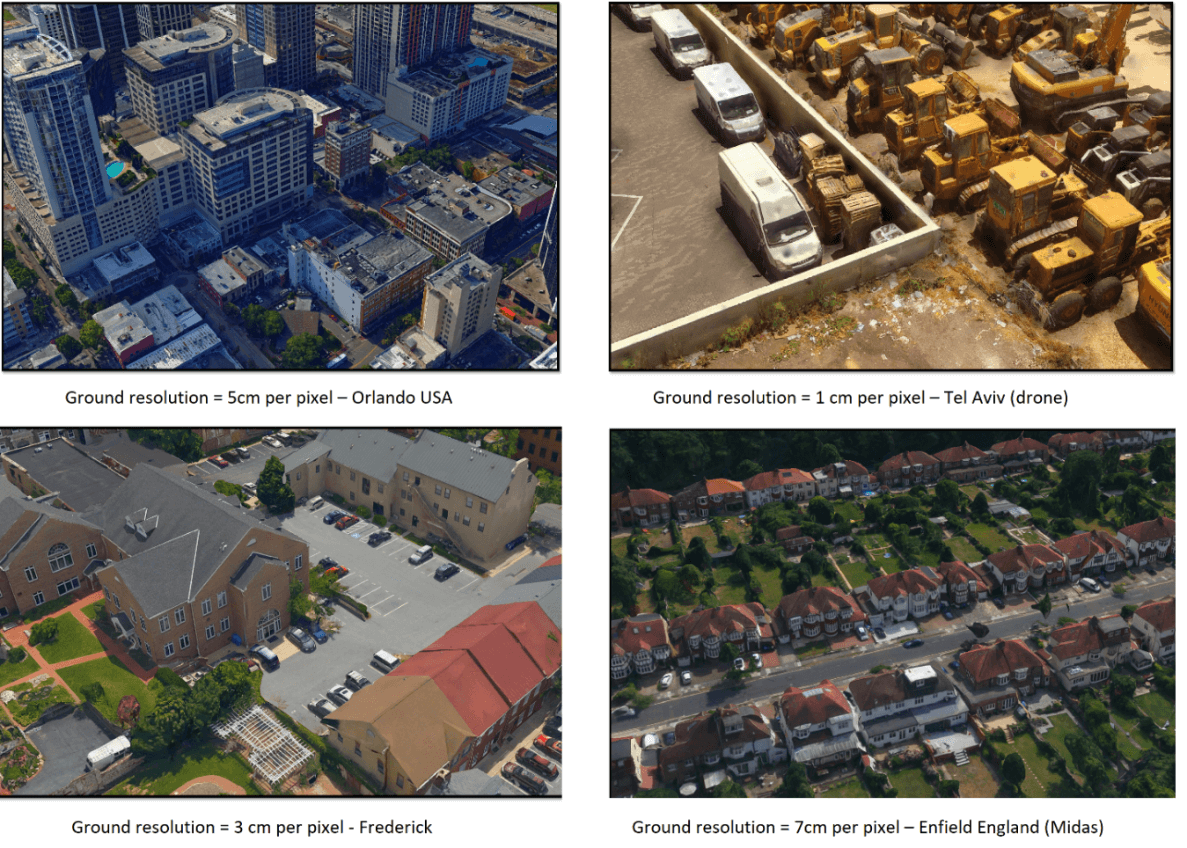
Step 1: Imagery Acquisition
The first step to creating a 3D model is imagery acquisition. All visible surfaces of the intended object or scene must be photographed from multiple overlapping viewpoints.
The accuracy of the resulting 3D mesh model is affected by several factors including: input image resolution and quality, lens distortion, overlapping ratio, directionality, and lighting. While PhotoMesh optimizes the accuracy of the 3D mesh model by selecting the best photos for an area, each factor can affect the overall output or cause varying levels of accuracy and quality in different areas of a project.
See "Imagery Acquisition" in the "Photo Management" chapter for more information.
Step 2: Creating a PhotoMesh Project
Before beginning to work in PhotoMesh, you must create a new project or open an existing project. See "Creating and Opening a PhotoMesh Project" in the "Getting Started" chapter for more information.
Step 3: Loading Photos and Other Input Sources and Preparing the Project
Photos and other input sources are loaded into a project using any of the following methods:
§ Load photo files from disk (JPG, TIF, IIQ).
§ Load an Excel/XML file with a list of photos, their file paths, all photo information (e.g., XYZ, OPK/YPR) and photo collection and camera information (e.g., focal length, sensor width, pixel size).
§ Load a CSV file with a list of photos, their file paths and XYZ and OPK/YPR photo information.
§ Load a PhotoMesh project. When a PhotoMesh project (.PhotoMeshXML) is loaded into a second project, only the project’s photos and photo and collection parameters are loaded.
§ Load a video from which PhotoMesh extracts individual image frames.
§ Import photos of different data types (e.g., Inpho, Bingo, Stellacore) into the project with their metadata (e.g., sensor width, focal length, and aerotriangulation data). When AT results are imported, the AT step of the build process can be skipped (by selecting "Do not calculate AT (Fully trusted)" in the Calculation Mode AT parameter).
§ Load LiDAR data in .las, .laz or .e57 formats into a PhotoMesh project, integrating it with project photos to supplement project data and increase model accuracy.
See "Loading Photos" and "Importing Photos with Metadata" in the "Photo Management" chapter, and "Loading LiDAR Data" in the "LiDAR Management" chapter for information.
After photos have been loaded, do any of the following to prepare the project for the build:
§ Modify photo and photo collection properties
§ Verify that the camera symbols generate the expected cluster form
§ Project photos on the terrain to see if they fit the terrain imagery or to better understand their position
§ Show LiDARs on the terrain to see if they fit the terrain imagery or to better understand their position
§ Associate a LiDAR with its trajectory data that provides information about the scanner’s position while capturing the point cloud
§ Improve the accuracy of the model’s position by creating ground control points that associate real-world X, Y, Z coordinates with corresponding locations (in pixels) in photos
§ Establish a correspondence between project photos and improve aerotriangulation results by creating tie points in the same physical point in three or more photos
§ View photos in the photo viewer
§ Import or draw water body polygons to generate a flat surface with correct texturing over user-defined water bodies
§ Display the directions map to identify which areas of the project have sufficient coverage and which require more
§ Display the overlap map
§ Create a subset AT area in which to validate camera parameters and build settings
§ Set a reconstruction area
See "Modifying Photo and Photo Collection Properties" in the "Photo Management" chapter, "Working with Water Body Polygons" in the "Reviewing your Build" chapter and the "LiDAR Management", "Preparing the Project", and "Control Points" chapters for information.
Step 4: Managing Local, Pool, and AWS Fusers
Fusers allow you to share the demanding workload involved in processing the different build steps (data preparation, AT, point cloud, mesh model, texture, 3DML/other outputs) between several computers on the same local network. The master computer utilizes the computing power of the network’s client computers by connecting to PhotoMesh fusers on the client machines.
Fusers can be shared between several PhotoMesh Build Managers in your organization, enabling each machine running PhotoMesh to use the combined resources of all the machines in the pool. PhotoMesh can also work with Amazon Web Services (AWS), adding and terminating virtual fuser machines, to scale a project up and down based on resource needs.
See "Installing PhotoMesh Fusers" and "Uninstalling PhotoMesh Fusers" in the "Getting Started" chapter for information on installing and starting the fusers. See "Fuser Management (on the Master computer)" and "Fuser Auto-Scaling" in the "Fusers" chapter for information on managing the fusers, and the "Getting Started with AWS" chapter for information about AWS fusers.
Step 5: Building the Model
After all photos are added to the project and all properties are set as required, you can launch PhotoMesh Build Manager to begin the build process. The build process provides flexibility both with regard to the area of the project being built (entire or selected area) and the build steps that are to be performed. To achieve optimal results and avoid unnecessary rebuilding, it is recommended to initially perform only the aerotriangulation step ("AT Only"), and then review the results, to ensure a precise AT which includes all project’s photos that intersect with the AT area, before proceeding with the rest of the build. When an AT Only build is repeated following project adjustments, PhotoMesh determines precisely which tiles and which specific AT sub-processes were affected by the modification of properties or control points, enabling a much lighter and faster AT process.
The build process involves the following steps:
§ Data Preparation
§ Conversion of photos to PhotoMesh's internal format (SMPT)
§ Conversion of LiDAR to PhotoMesh's internal format (CPT)
§ Color correction of photos
§ Aerotriangulation
§ Reconstruction
§ Point Cloud Creation
§ Model Creation
§ Model Texturing
§ Project Output - Select all required output formats: 3DML (for loading directly into TerraExplorer and streaming with SkylineGlobe Server), DAE, OBJ, 3D Tiles, SLPK (I3S), OSGB, Orthophoto, DSM, DTM/DEM, and LAS (Point cloud public file format). See "Setting Build Steps, Parameters, and Outputs" in the "Building" chapter for information on the different file formats.
See the "Building" chapter for information.
Note: PhotoMesh also supports the integration of external tools and scripts, allowing on-the-fly processing of each photo loaded into the project. See “Preprocessing and Postprocessing of Photos Using PhotoMesh Hooks” in the “Building” chapter for more information.
Step 6: Managing and Reviewing the Build
Throughout the build process, you can monitor build progress from PhotoMesh Build Manager and view the build data already created in the PhotoMesh 3D Window. As soon as a build step is completed for a tile, its build data is viewable in the 3D Window, e.g. if aerotriangulation was performed, PhotoMesh can display the calculated camera positions in the 3D Window, and if reconstruction tiles were calculated, they can be displayed in the 3D Window, with each tile colorized according to the build step completed. You can also view point cloud, 3D model, and texture data for one or more tiles once this build step for the selected tile is completed. Build quality and production reports are available, as well, with statistical and graphical information about the build process. See "Reviewing Aerotriangulation and Reconstruction Tiles" in the "Reviewing Your Build" chapter for information.
After a build is complete, water bodies can be defined by drawing or importing a water body polygon, and mesh imperfections, such as bumps, irregular surfaces, or floating artifacts, can be marked for flattening, filling, and clean up using the Manual Retouch tool. See "Working with Water Body Polygons" and "Marking a Mesh Layer for Retouching" in the "Reviewing Your Build" chapter for information.
After reviewing build data, you can easily rebuild any of the following: the entire project, error tiles, or selected tiles. See "Monitoring a Build" in the "Building" chapter and the "Reviewing Your Build" chapter for information. Alternatively, you can create a new build version with different project steps and different build parameters. You have the option to create a completely new build version or one which copies the AT information from the previous build, thereby accelerating the build process. See "Creating a New Build Version" and "Creating a New Build Version with a Copy of the Current Aerotriangulation Results" in the "Building" chapter for information.
Before rebuilding, 3D models can be exported when necessary to external software, such as Autodesk® MeshMixer, to perform certain edits, e.g. to remove a particular building that is being torn down, flatten surfaces and correct certain imperfections such as bumps or irregular surfaces, or edit textures, and then reimported to PhotoMesh. See "Importing and Exporting Models" in the “Reviewing Your Build” chapter for more information.